Table of Contents
- Introduction to Diodes
- Diode Testing Equipment
- Testing Regular Diodes
- Forward Bias Test
- Reverse Bias Test
- Testing Zener Diodes
- Forward Bias Test for Zener Diodes
- Reverse Bias Test for Zener Diodes
- Testing Light Emitting Diodes (LEDs)
- Testing Schottky Diodes
- Testing Varactor Diodes
- Diode Testing in Circuits
- In-Circuit Diode Testing
- Out-of-Circuit Diode Testing
- Frequently Asked Questions (FAQ)
- Conclusion
Introduction to Diodes
Diodes are two-terminal semiconductor devices that allow current to flow in one direction while blocking current in the opposite direction. They are used in various applications, such as rectification, voltage regulation, and protection against voltage spikes. There are several types of diodes, each with unique characteristics and purposes:
- Regular diodes
- Zener diodes
- Light Emitting Diodes (LEDs)
- Schottky diodes
- Varactor diodes
To ensure that diodes are functioning properly, it is essential to test them using appropriate techniques based on their type and application.
Diode Testing Equipment
Before discussing specific Diode Testing Techniques, let’s review the equipment commonly used for testing diodes:
-
Digital Multimeter (DMM): A versatile tool that can measure voltage, current, and resistance. Most DMMs have a dedicated diode test function.
-
Analog Multimeter: Similar to a DMM but with an analog display. Analog multimeters can be used for diode testing, but they may not have a dedicated diode test function.
-
Oscilloscope: An instrument that displays voltage waveforms over time. Oscilloscopes can be used to analyze diode behavior in dynamic circuits.
-
Power Supply: A device that provides a stable and adjustable voltage source for testing diodes under different conditions.
Testing Regular Diodes
Regular diodes, also known as rectifier diodes, are the most common type of diode. They are used for rectification, which converts alternating current (AC) to direct current (DC). To test a regular diode, you can perform a forward bias test and a reverse bias test using a DMM.
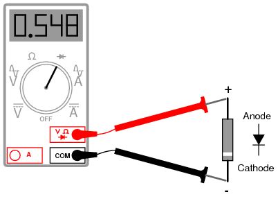
Forward Bias Test
- Set your DMM to the diode test function, usually denoted by a diode symbol.
- Connect the red probe (positive) to the anode and the black probe (negative) to the cathode of the diode.
- The DMM should display a voltage drop across the diode, typically between 0.5V and 0.8V for silicon diodes and 0.2V to 0.4V for germanium diodes.
If the DMM displays “OL” (open loop) or a very high resistance value, the diode is likely open or damaged.
Reverse Bias Test
- Set your DMM to the diode test function.
- Connect the red probe (positive) to the cathode and the black probe (negative) to the anode of the diode.
- The DMM should display “OL” or a very high resistance value, indicating that the diode is blocking current in the reverse direction.
If the DMM displays a low resistance or voltage drop, the diode is likely shorted or damaged.
Here is a table summarizing the expected results for a regular diode test:
| Test | Expected Result |
|---|---|
| Forward Bias | Silicon: 0.5V to 0.8V Germanium: 0.2V to 0.4V |
| Reverse Bias | “OL” or very high resistance |
Testing Zener Diodes
Zener diodes are designed to allow current to flow in the reverse direction when the voltage across the diode exceeds a specific value, known as the Zener voltage. They are commonly used for voltage regulation and protection against overvoltage. Testing Zener diodes involves performing a forward bias test and a reverse bias test.
Forward Bias Test for Zener Diodes
Follow the same steps as the forward bias test for regular diodes. The expected voltage drop should be similar to that of a regular diode (0.5V to 0.8V for silicon, 0.2V to 0.4V for germanium).
Reverse Bias Test for Zener Diodes
- Set your DMM to the diode test function.
- Connect the red probe (positive) to the cathode and the black probe (negative) to the anode of the Zener diode.
- The DMM should display the Zener voltage, which is the voltage at which the diode starts conducting in the reverse direction.
If the DMM displays “OL” or a very high resistance value, the Zener diode is likely open or damaged. If the displayed voltage is significantly different from the specified Zener voltage, the diode may be faulty.
Here is a table summarizing the expected results for a Zener diode test:
| Test | Expected Result |
|---|---|
| Forward Bias | Silicon: 0.5V to 0.8V Germanium: 0.2V to 0.4V |
| Reverse Bias | Zener voltage (as specified in the datasheet) |
Testing Light Emitting Diodes (LEDs)
LEDs are diodes that emit light when current flows through them in the forward direction. They are used in various applications, such as indicators, displays, and lighting. Testing LEDs involves a visual inspection and a forward bias test.
-
Visual Inspection: Check the LED for any physical damage, such as cracks or a broken lens.
-
Forward Bias Test:
- Set your DMM to the diode test function.
- Connect the red probe (positive) to the anode (longer lead) and the black probe (negative) to the cathode (shorter lead) of the LED.
- The LED should illuminate, and the DMM should display a voltage drop between 1.8V and 3.3V, depending on the LED color and type.
If the LED does not illuminate or the DMM displays “OL” or a very high resistance value, the LED is likely open or damaged.
Testing Schottky Diodes
Schottky diodes are designed for fast switching and low forward voltage drop. They are commonly used in high-frequency and low-voltage applications. Testing Schottky diodes is similar to testing regular diodes, with a forward bias test and a reverse bias test.
- Forward Bias Test:
- Set your DMM to the diode test function.
- Connect the red probe (positive) to the anode and the black probe (negative) to the cathode of the Schottky diode.
-
The DMM should display a voltage drop between 0.2V and 0.4V.
-
Reverse Bias Test:
- Set your DMM to the diode test function.
- Connect the red probe (positive) to the cathode and the black probe (negative) to the anode of the Schottky diode.
- The DMM should display “OL” or a very high resistance value.
If the DMM displays a low resistance or voltage drop during the reverse bias test, the Schottky diode is likely shorted or damaged.
Testing Varactor Diodes
Varactor diodes, also known as variable capacitance diodes or tuning diodes, are diodes whose capacitance varies with the applied reverse voltage. They are used in applications such as voltage-controlled oscillators and tuning circuits. Testing varactor diodes involves measuring their capacitance at different reverse voltages.
- Set your DMM to the capacitance measurement function.
- Connect the red probe (positive) to the cathode and the black probe (negative) to the anode of the varactor diode.
- Apply different reverse voltages using a power supply and measure the corresponding capacitance values.
Compare the measured capacitance values with the specifications in the varactor diode’s datasheet to determine if the diode is functioning correctly.
Diode Testing in Circuits
Diode testing can be performed in-circuit or out-of-circuit, depending on the accessibility and the nature of the problem.
In-Circuit Diode Testing
In-circuit testing involves testing the diode while it is still connected to the circuit. This method is useful when the diode is not easily accessible or when you want to check the diode’s performance under actual operating conditions. However, in-circuit testing can be challenging due to the influence of other components in the circuit.
To perform in-circuit diode testing:
1. Set your DMM to the diode test function.
2. Connect the probes to the diode’s terminals, ensuring that you maintain the correct polarity (red probe to anode, black probe to cathode).
3. Observe the DMM readings and compare them with the expected values for the specific type of diode.
If the readings deviate significantly from the expected values, the diode may be faulty, or there might be other issues in the circuit affecting the diode’s performance.
Out-of-Circuit Diode Testing
Out-of-circuit testing involves removing the diode from the circuit and testing it in isolation. This method eliminates the influence of other components and allows for more accurate testing. Out-of-circuit testing is preferred when the diode is easily accessible or when you suspect that the diode is faulty.
To perform out-of-circuit diode testing:
1. Safely remove the diode from the circuit, ensuring that you note its orientation (anode and cathode).
2. Follow the testing procedures for the specific type of diode (regular, Zener, LED, Schottky, or varactor) as described in the previous sections.
3. Compare the DMM readings with the expected values for the diode type.
If the readings indicate that the diode is faulty, replace it with a new one and retest the circuit to confirm that the issue has been resolved.
Frequently Asked Questions (FAQ)
- What is the difference between a regular diode and a Zener diode?
-
A regular diode allows current to flow only in the forward direction, while a Zener diode is designed to allow current to flow in the reverse direction when the voltage across the diode exceeds a specific value (Zener voltage).
-
Can a DMM be used to test all types of diodes?
-
Yes, a DMM with a diode test function can be used to test most types of diodes, including regular diodes, Zener diodes, LEDs, and Schottky diodes. However, for varactor diodes, a DMM with a capacitance measurement function is required.
-
What should I do if a diode fails the testing procedure?
-
If a diode fails the testing procedure, it is likely faulty and should be replaced with a new one. After replacing the diode, retest the circuit to ensure that the issue has been resolved.
-
Can a diode be tested while it is still connected to the circuit?
-
Yes, diodes can be tested in-circuit. However, in-circuit testing can be challenging due to the influence of other components in the circuit. For more accurate results, out-of-circuit testing is recommended whenever possible.
-
What is the purpose of testing a diode?
- Testing a diode ensures that it is functioning correctly and helps troubleshoot issues in electronic circuits. By identifying faulty diodes, you can prevent potential problems and maintain the proper operation of electronic devices.
Conclusion
Diode testing is a crucial skill for anyone working with electronic circuits. By understanding the different types of diodes and their testing techniques, you can effectively troubleshoot and maintain electronic devices. Remember to use the appropriate testing equipment and follow the correct procedures based on the type of diode being tested.
Regular diodes, Zener diodes, LEDs, Schottky diodes, and varactor diodes each have their unique characteristics and testing requirements. Testing can be performed in-circuit or out-of-circuit, depending on the accessibility and the nature of the problem.
By mastering diode testing techniques, you can quickly identify faulty components, prevent potential issues, and ensure the proper functioning of electronic circuits. Always refer to the diode’s datasheet for specific information and consult with experienced professionals when in doubt.


Leave a Reply