Introduction to Touch Lamp Circuits
A touch lamp circuit is an electronic circuit that allows a lamp to be turned on or off simply by touching a conductive surface. This type of circuit senses the capacitance of the human body and uses it to trigger the switching of the lamp. Touch lamp circuits provide a convenient and intuitive way to control lighting without the need for traditional mechanical switches.
In this article, we will explore the principles behind touch lamp circuits, their components, and how to design and build your own human-touch sensitive circuit for touch lamps. We will also discuss various applications and advantages of touch lamp circuits.
How Touch Lamp Circuits Work
Capacitive Sensing
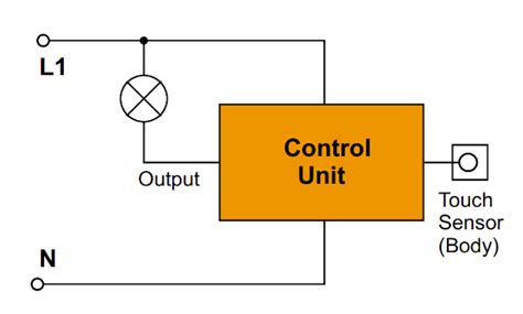
The core principle behind touch lamp circuits is capacitive sensing. When a conductive object, such as a human finger, comes into contact with or in close proximity to a touch sensor, it alters the capacitance of the sensor. The circuit detects this change in capacitance and uses it as a trigger to switch the lamp on or off.
The human body acts as a capacitor when it comes into contact with the touch sensor. The capacitance of the human body is typically in the range of 100-300 picofarads (pF). When the body touches the sensor, it forms a capacitive coupling with the sensor, which changes the overall capacitance of the system.
Sensitivity Adjustment
Touch lamp circuits often include sensitivity adjustment mechanisms to fine-tune the responsiveness of the touch sensor. This is important because the capacitance of the human body can vary depending on factors such as skin moisture, contact area, and environmental conditions.
The sensitivity adjustment allows the user to set the threshold at which the circuit responds to touch. It ensures that the lamp switches reliably when touched intentionally while avoiding false triggers from accidental touches or nearby objects.
Debouncing and Latching
Touch lamp circuits incorporate debouncing and latching mechanisms to provide stable and consistent operation. Debouncing is necessary because the human touch can introduce momentary fluctuations in the capacitance readings. Without debouncing, these fluctuations can cause the lamp to flicker or switch erratically.
Debouncing is typically implemented using a capacitor and a resistor network that filters out the brief fluctuations and ensures a clean and stable trigger signal. The debounce time is adjusted to match the expected duration of a deliberate touch.
Latching is used to maintain the state of the lamp after the touch is released. Once the lamp is switched on by a touch, it remains on until another touch is detected, even if the finger is removed from the sensor. Latching is achieved using a bistable circuit, such as a flip-flop or a thyristor, which holds the state until a reset signal is received.

Components of a Touch Lamp Circuit
A typical touch lamp circuit consists of the following components:
-
Touch Sensor: The touch sensor is the conductive surface that detects the presence of a human touch. It can be a metal plate, a conductive pad, or any other conductive material that allows capacitive coupling with the human body.
-
Microcontroller: A microcontroller is the brain of the touch lamp circuit. It processes the touch sensor input, performs debouncing and latching, and controls the switching of the lamp. Popular microcontrollers for touch lamp circuits include Arduino, PIC, and AVR.
-
Sensitivity Adjustment: The sensitivity adjustment component allows the user to fine-tune the responsiveness of the touch sensor. It can be implemented using a potentiometer or a digital potentiometer controlled by the microcontroller.
-
Debounce Circuit: The debounce circuit filters out the momentary fluctuations in the touch sensor signal caused by the human touch. It typically consists of a capacitor and resistor network that introduces a small delay to stabilize the signal.
-
Latching Circuit: The latching circuit maintains the state of the lamp after the touch is released. It can be implemented using a flip-flop, a thyristor, or a relay, depending on the specific design requirements.
-
Lamp Driver: The lamp driver is responsible for switching the lamp on or off based on the output from the microcontroller. It can be a solid-state relay (SSR), a TRIAC, or a MOSFET, depending on the type and power rating of the lamp.
-
Power Supply: The power supply provides the necessary voltage and current to operate the touch lamp circuit and the lamp itself. It can be a standalone power supply unit or integrated into the circuit board.

Designing a Touch Lamp Circuit
When designing a touch lamp circuit, several key considerations need to be taken into account:
Touch Sensor Design
The touch sensor is a critical component of the touch lamp circuit. It should be designed to provide reliable and sensitive touch detection while being aesthetically pleasing and easy to integrate into the lamp structure.
Some common touch sensor designs include:
- Metal plates: A simple metal plate can serve as a touch sensor. It can be shaped and sized to match the lamp design and mounted on the lamp surface.
- Conductive pads: Conductive pads are flat, adhesive-backed sensors that can be easily attached to the lamp surface. They are available in various sizes and shapes to suit different lamp designs.
- Conductive Paint: Conductive paint can be applied directly onto the lamp surface to create a custom touch sensor. It allows for flexibility in sensor shape and size.
When selecting the touch sensor material and design, consider factors such as conductivity, durability, and ease of integration with the lamp structure.
Microcontroller Selection
The choice of microcontroller for the touch lamp circuit depends on the complexity of the design and the desired features. Some popular microcontroller options include:
- Arduino: Arduino boards, such as the Arduino Uno or Arduino Nano, are widely used in touch lamp circuits due to their ease of use, extensive library support, and large community.
- PIC: PIC microcontrollers, offered by Microchip Technology, are another common choice for touch lamp circuits. They are known for their low power consumption and wide range of peripherals.
- AVR: AVR microcontrollers, such as the ATmega series, are also suitable for touch lamp circuits. They offer good performance, low power consumption, and a rich set of peripherals.
When selecting a microcontroller, consider factors such as the number of I/O pins required, memory size, processing speed, and available peripherals.
Sensitivity Adjustment
Incorporating a sensitivity adjustment mechanism in the touch lamp circuit allows users to fine-tune the responsiveness of the touch sensor to their preferences and environmental conditions.
| Adjustment Method | Description |
|---|---|
| Potentiometer | A potentiometer can be used to manually adjust the sensitivity threshold. The user can turn the potentiometer knob to increase or decrease the sensitivity. |
| Digital Potentiometer | A digital potentiometer is controlled by the microcontroller and allows for programmatic adjustment of the sensitivity. The microcontroller can read the touch sensor input and dynamically adjust the sensitivity based on predefined algorithms. |
| Capacitive Divider | A capacitive divider circuit can be used to adjust the sensitivity by changing the ratio of the capacitance between the touch sensor and a reference capacitor. The microcontroller can control the divider ratio to achieve the desired sensitivity level. |
Debounce and Latching
Debouncing and latching are essential for ensuring stable and consistent operation of the touch lamp circuit. The debounce circuit filters out the momentary fluctuations caused by the human touch, while the latching circuit maintains the state of the lamp after the touch is released.
| Circuit | Description |
|---|---|
| RC Debounce | An RC (resistor-capacitor) debounce circuit introduces a small delay to filter out the brief fluctuations. The resistor and capacitor values are chosen based on the expected duration of a deliberate touch. |
| Software Debounce | Software debouncing can be implemented in the microcontroller firmware. It involves reading the touch sensor input multiple times within a specified time window and determining the stable state based on the majority of the readings. |
| Flip-Flop Latch | A flip-flop circuit, such as an SR (Set-Reset) flip-flop, can be used to latch the state of the lamp. When a touch is detected, the flip-flop is set, and the lamp turns on. Another touch resets the flip-flop, turning the lamp off. |
| Thyristor Latch | A thyristor, such as a TRIAC or an SCR (Silicon Controlled Rectifier), can be used as a latching element. Once triggered by a touch, the thyristor conducts and latches the lamp in the on state until the power is cycled or a reset signal is applied. |
Lamp Driver
The lamp driver circuit is responsible for switching the lamp on or off based on the output from the microcontroller. The choice of lamp driver depends on the type and power rating of the lamp being controlled.
| Lamp Driver | Description |
|---|---|
| Solid-State Relay (SSR) | An SSR is an electronic switching device that provides isolation between the control circuit and the lamp. It is suitable for controlling AC-powered lamps and can handle higher power loads. |
| TRIAC | A TRIAC is a bidirectional thyristor that can switch AC loads. It is commonly used for dimming and on/off control of AC lamps. The microcontroller generates the appropriate trigger signals to control the TRIAC. |
| MOSFET | A MOSFET (Metal-Oxide-Semiconductor Field-Effect Transistor) is used for switching DC loads, such as LED lamps. The microcontroller controls the gate of the MOSFET to turn the lamp on or off. |
When selecting the lamp driver, consider the voltage and current requirements of the lamp, the desired switching speed, and any additional features like dimming or soft-start.

Building a Touch Lamp Circuit
Building a touch lamp circuit involves the following steps:
-
Gather the necessary components, including the touch sensor, microcontroller, sensitivity adjustment components, debounce and latching circuits, lamp driver, and power supply.
-
Design the circuit schematic based on the chosen components and the desired features. Use circuit design software or draw the schematic manually.
-
Assemble the circuit on a breadboard or prototyping board for initial testing and debugging. Ensure proper connections and double-check the wiring.
-
Write the microcontroller firmware to handle touch sensing, debouncing, latching, and lamp control. Use the appropriate programming language and libraries for the selected microcontroller.
-
Test the circuit functionality by touching the touch sensor and observing the lamp behavior. Fine-tune the sensitivity adjustment and debounce settings if necessary.
-
Design a custom PCB (Printed Circuit Board) for the touch lamp circuit based on the finalized schematic. Consider factors such as component placement, trace routing, and ground planes for optimal performance.
-
Fabricate the PCB and solder the components onto it. Perform a visual inspection and continuity tests to ensure proper assembly.
-
Integrate the PCB into the lamp structure, ensuring secure and reliable connections between the touch sensor, lamp, and power supply.
-
Perform final testing and calibration of the touch lamp circuit in the actual lamp environment. Verify the touch sensitivity, lamp switching, and overall functionality.
-
Optionally, add additional features such as dimming, multiple touch modes, or remote control capabilities to enhance the functionality of the touch lamp.
Applications and Advantages of Touch Lamp Circuits
Touch lamp circuits find applications in various settings, including:
-
Home lighting: Touch lamps provide a convenient and intuitive way to control room lighting without the need for traditional switches. They can be used as bedside lamps, desk lamps, or decorative lighting fixtures.
-
Hospitality industry: Touch lamps are commonly used in hotels, restaurants, and lounges to create a modern and interactive lighting experience for guests.
-
Retail displays: Touch-sensitive lighting can be incorporated into product displays and showcases to attract attention and engage customers.
-
Assistive technology: Touch lamps can be beneficial for individuals with limited mobility or dexterity, as they eliminate the need for physical switches.
The advantages of touch lamp circuits include:
-
Convenience: Touch control provides a simple and intuitive way to operate lamps without the need for mechanical switches or remote controls.
-
Aesthetics: Touch lamps offer a sleek and modern design, eliminating the clutter of visible switches and enhancing the overall appearance of the lamp.
-
Durability: Touch sensors have no moving parts, making them more durable and long-lasting compared to mechanical switches that can wear out over time.
-
Customization: Touch lamp circuits can be customized to suit specific lamp designs and user preferences. The sensitivity, debounce time, and latching behavior can be adjusted to optimize the user experience.
-
Energy efficiency: Touch lamps can incorporate energy-saving features such as automatic shutoff or dimming based on touch patterns or duration, contributing to overall energy efficiency.
Conclusion
Touch lamp circuits provide an innovative and convenient way to control lighting through human touch. By utilizing capacitive sensing, these circuits detect the presence of a human body and switch the lamp on or off accordingly. The design of a touch lamp circuit involves careful consideration of the touch sensor, microcontroller, sensitivity adjustment, debouncing, latching, and lamp driver components.
Building a touch lamp circuit requires knowledge of electronic components, circuit design, and microcontroller programming. With the right components and design considerations, a reliable and responsive touch lamp circuit can be created to enhance the lighting experience in various settings.
Touch lamp circuits offer numerous advantages, including convenience, aesthetics, durability, customization, and energy efficiency. As touch-based interfaces continue to gain popularity, touch lamp circuits are expected to find increasing applications in both residential and commercial environments.
FAQs
-
Q: Can a touch lamp circuit be used with any type of lamp?
A: Touch lamp circuits can be used with a wide range of lamps, including incandescent, LED, and CFL lamps. However, the lamp driver circuit needs to be chosen based on the specific type and power rating of the lamp to ensure compatibility and safe operation. -
Q: How do I adjust the sensitivity of a touch lamp circuit?
A: The sensitivity of a touch lamp circuit can be adjusted using a potentiometer, a digital potentiometer, or a capacitive divider circuit. By changing the resistance or capacitance ratio, the sensitivity threshold can be fine-tuned to suit the user’s preferences and environmental conditions. -
Q: Is it necessary to use a microcontroller in a touch lamp circuit?
A: While a microcontroller is not strictly necessary for a basic touch lamp circuit, it offers several advantages. A microcontroller allows for more advanced features like sensitivity adjustment, debouncing, latching, and additional functionalities such as dimming or multiple touch modes. It provides flexibility and programmability to enhance the overall functionality of the touch lamp. -
Q: Can a touch lamp circuit be powered by batteries?
A: Yes, a touch lamp circuit can be powered by batteries. The power supply section of the circuit needs to be designed to accommodate the voltage and current requirements of the microcontroller, touch sensor, and lamp driver. Low-power microcontrollers and efficient lamp drivers can be chosen to optimize battery life. -
Q: Are touch lamp circuits safe to use?
A: Touch lamp circuits are generally safe to use when designed and built properly. Proper isolation between the high-voltage lamp circuit and the low-voltage control circuit is essential to ensure user safety. The use of solid-state relays, opto-isolators, or other isolation techniques helps prevent electrical hazards. Additionally, the touch sensor should be designed to operate at a safe voltage level to avoid any risk of electric shock.


Leave a Reply