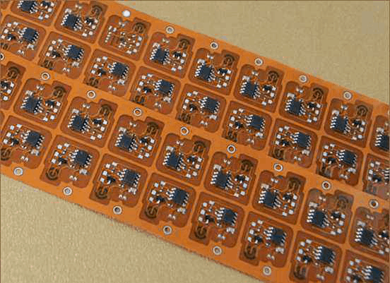
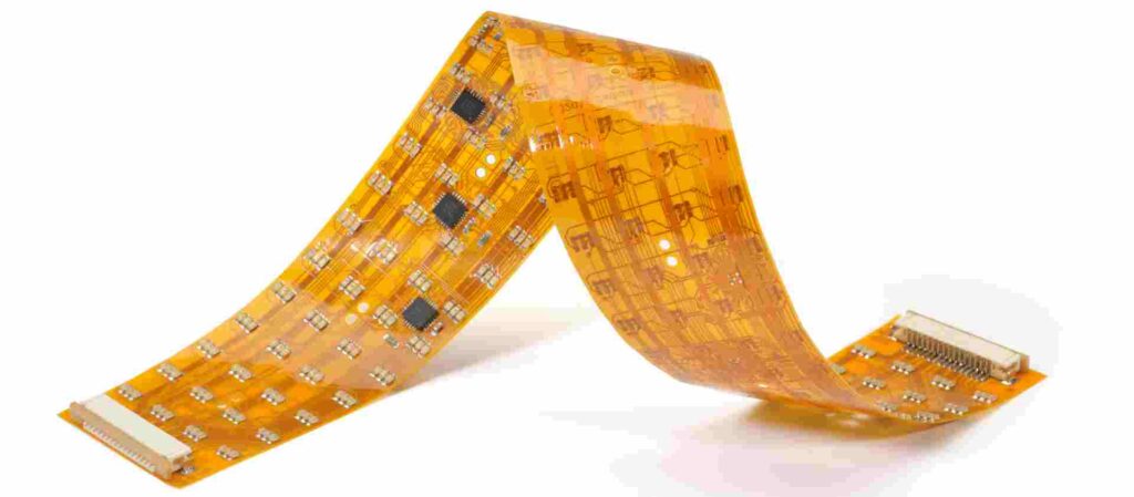
Introduction to Flex PCBs
A flexible printed circuit board (flex PCB or flex circuit) is a type of printed circuit board made of flexible materials like polyimide that can bend and flex. Flex PCBs consist of conductive traces etched from copper sheets and laminated onto a flexible dielectric substrate. They are commonly used in electronic devices where flexibility, space savings, or movement is required. Some advantages of flex PCBs:
- Can bend and flex to fit tight spaces
- Reduce wiring and soldering
- Allow movement and adjustability
- Lightweight and durable
- Cost effective for medium to high production runs
However, flex PCBs can be more challenging to assemble and solder than rigid boards. Proper flex PCB soldering technique is important to create reliable solder joints without damaging the flexible materials. This article covers key considerations and best practices for soldering flex PCB assemblies.
Flex PCB Soldering Challenges
Flex circuits present some unique challenges for soldering:
Flexing and Bending
Since flex PCBs are designed to flex, they can be more difficult to hold flat and stable during soldering. The flexing can put stress on components and solder joints.
Heat Tolerance
Most flex circuit materials have relatively low maximum temperature tolerances of around 150°C. Excessive heat during soldering can damage the substrate.
Plated Through Holes
Many flex PCBs have plated through holes (PTHs) to allow connections between layers. The plating in the holes can spread heat and be damaged by overheating.
Fine Pitch and High Density
Flex PCBs often have fine pad geometries and spacing to save space. This makes soldering more difficult.
Difficult Access
Compact flex circuits with components on both sides can make soldering access challenging.
Flex PCB Soldering Best Practices
Here are some tips for soldering flex PCBs:
Use Appropriate Soldering Tools
- Soldering iron – Use a temperature controlled iron with a fine tip around 1.5-3mm. Adjust temperature between 315-370°C based on specific materials.
- Solder – Use a “no-clean” solder with flux core, preferably lead-free alloy with low residue.
- Soldering aids – Use tools like mini vises, clamps, stencils, or jigs to hold the flex PCB stable.
Prepare the Work Area
- Use an anti-static mat to prevent ESD damage to components.
- Have a clean, well-lit and organized workspace.
- Position any inspection tools like magnifiers or microscopes.
Modify Technique
- Use a lower soldering iron temperature and work quickly to limit heat exposure.
- Apply soldering iron to joint, not component body, to avoid damaging parts.
- Keep iron tip clean and retin. Tin tip with fresh solder before each joint.
- Use fine tip conical or chisel designs optimized for SMT soldering.
- Apply only enough solder to form joint without excess.
- Make fluid motions and avoid applying iron to one spot for too long.
- Allow extra time for joints to cool before moving or flexing PCB.
Inspect Joints
- Visually inspect each solder connection under magnification.
- Reflow any joints with gaps, shorts, poor wetting or other defects.
- Remove all solder flux residue to avoid corrosion or electrical issues.
- Functionally test circuitry after soldering for full defect screening.
- Take extra care inspecting hidden or dual-side joints. Use mirrors as needed.
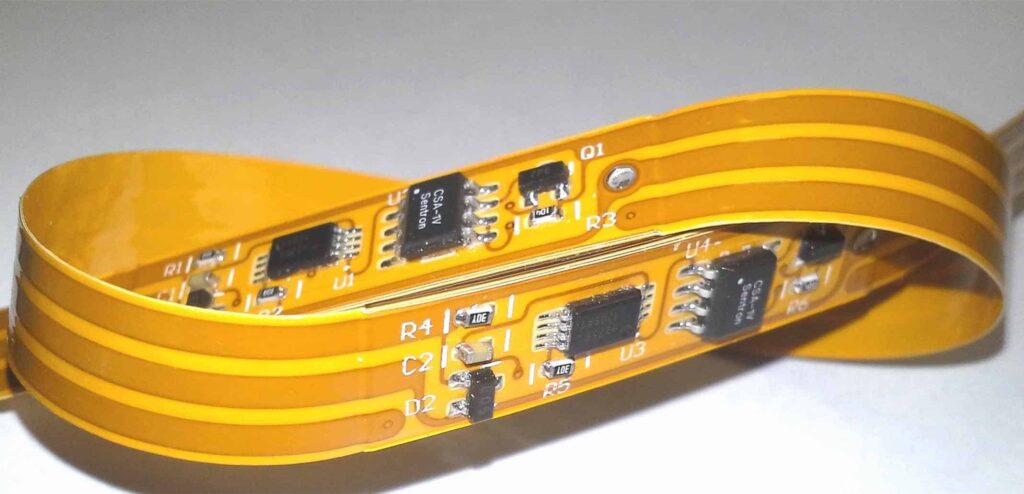
Soldering Flex PCB Components
In addition to general guidelines, here are tips for soldering specific component types on flex PCB assemblies:
Surface Mount Devices (SMDs)
- Use non-contact preheating on larger SMDs to avoid thermal shock.
- For large components, heat sink the body and apply soldering iron only to terminals.
- Take care not to exceed temperature limits of packages like plastic QFNs or BGAs.
- Realign shifted SMTs before soldering using tweezers or pick and place tools.
- Use solder paste printing or dispensing for best results with fine pitch ICs.
Plated Through Holes (PTHs)
- Avoid overheating PTHs to prevent damage to plating walls inside holes.
- For PTH components like connectors, apply heat mainly to the lead, then contact pad last.
- Carefully trim excess leads without damaging pads or conductive fingers.
Board Stiffeners
- Attach stiffeners or heat sinks to board with thermo-adhesive or glue.
- Prevent solder wicking on stiffener joints by using thermal reliefs in copper pads.
- Avoid soldering stiffeners until all other joints are completed.
Edge Connectors
- Use conformal coating on edge fingers to prevent solder bridging.
- Inspect for shorts between adjacent connector fingers.
- Take care not to cut or damage connector fingers when trimming board edges.
Proper Flex PCB Handling
Maintaining the integrity of the flexible circuit board is also important during assembly steps:
- Avoid any sharp bending or folding of the flex board.
- Do not subject board to torsional twist or shear forces.
- Prevent dust, dirt or oil from contaminating surfaces.
- Use dedicated ESD-safe storage racks, tubes and packaging.
- Never touch the gold fingers of connectors except for soldering.
- Carefully route cables, wires and connectors to avoid flex damage.
- Attach strain relief devices for any cable or wire connections.
With the right tools, techniques, and care in handling, flex PCBs can be soldered effectively to create robust, reliable circuits. Proper flex PCB soldering practices will help prevent cracked joints, delamination, overheating damage, and other defects.
FAQ About Soldering Flex PCBs
1. What type of solder should be used for flex PCBs?
Lead-free solder with a “no clean” flux core designed for SMT soldering is recommended for flex PCBs. The solder should contain around 3% silver and 0.5% copper into the alloy for strength and conductivity. Low residue flux helps avoid buildup or contamination on the thin flex board conductors.
2. How can I prevent cracking solder joints on flex PCBs?
- Reflowing the solder joints after initial cooling helps to relieve stresses.
- Ensure the flex PCB is supported underneath during soldering to minimize bending.
- Avoid repeated flexing of the board in the area of solder joints.
- Use compliant adhesives to allow some movement between components and flex board.
3. What is the ideal soldering iron temperature for flex PCBs?
The optimal temperature is around 330 to 370°C. The temperature should be set based on the specific flex PCB material properties. Polyimide flex materials typically allow up to 200°C for short term exposure. Preheating the board can allow a lower iron temperature.
4. How can I hold a flex PCB steady during soldering?
Dedicated flex PCB holder tools are ideal for keeping the board flat and stable. Clips, clamps, mini vises, and soldering jigs can also be used. Double sided tapes, putty, or fixtures help hold the flex board in position during hand soldering or inspection.
5. What defects should I look out for when inspecting flex PCB solder joints?
- Cold solder joints with poor wetting or jagged edges.
- Excessive solder globs or bridges shorting traces.
- Cracked joints as a result of repeated flexing.
- Damage to the flexible substrate material like delamination or blistering.
- Bridging on finely pitched component leads.
- Residues or contamination left from solder flux.


Leave a Reply