Introduction to Capacitors on Circuit Boards
Capacitors are essential components in electronic circuits, playing a crucial role in storing and releasing electrical energy. When it comes to circuit boards, capacitors are widely used for various purposes, such as filtering, smoothing, and decoupling. In this comprehensive guide, we will delve into the world of capacitors on circuit boards, exploring their types, functions, and applications.
What is a Circuit Capacitor?
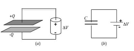
A circuit capacitor is a passive electronic component that stores electrical energy in an electric field. It consists of two conducting plates separated by an insulating material called a dielectric. The capacitance of a capacitor is measured in farads (F) and represents its ability to store charge.
Types of Capacitors Used on Circuit Boards
There are several types of capacitors commonly used on circuit boards, each with its own characteristics and applications. The following table summarizes the main types of capacitors:
| Capacitor Type | Dielectric Material | Typical Capacitance Range | Applications |
|---|---|---|---|
| Ceramic | Ceramic | pF to μF | High-frequency, decoupling, filtering |
| Electrolytic | Electrolyte | μF to mF | Power supply filtering, large capacitance |
| Tantalum | Tantalum pentoxide | μF to hundreds of μF | High-frequency, low-leakage, stable |
| Film | Plastic film | pF to μF | High-frequency, precision, low-loss |
| Mica | Mica | pF to nF | High-frequency, high-voltage, stable |
Functions of Capacitors on Circuit Boards
1. Filtering
One of the primary functions of capacitors on circuit boards is filtering. Capacitors can be used to remove unwanted noise, ripple, or interference from power supply lines or signal paths. By placing a capacitor in parallel with the load or in series with the signal, high-frequency components can be effectively filtered out, resulting in a cleaner and more stable signal.
Types of Capacitor Filters
- Low-pass filter: Allows low-frequency signals to pass while attenuating high-frequency components.
- High-pass filter: Allows high-frequency signals to pass while attenuating low-frequency components.
- Band-pass filter: Allows a specific range of frequencies to pass while attenuating frequencies outside that range.
- Notch filter: Attenuates a specific frequency or a narrow range of frequencies.
2. Decoupling
Decoupling is another important function of capacitors on circuit boards. In digital circuits, sudden changes in current consumption can cause voltage fluctuations on the power supply lines, leading to unwanted noise and signal integrity issues. Decoupling capacitors are placed close to the power pins of integrated circuits (ICs) to provide a local reservoir of charge, minimizing voltage fluctuations and ensuring stable operation.
Decoupling Capacitor Placement
- Bulk decoupling: Large capacitors (typically electrolytic or tantalum) are placed near the power entry point of the circuit board to filter low-frequency noise.
- Local decoupling: Smaller capacitors (usually ceramic) are placed close to the power pins of individual ICs to provide high-frequency decoupling.
3. Energy Storage
Capacitors can also be used for energy storage purposes on circuit boards. In applications such as power supplies, capacitors are employed to store energy during the charging phase and release it during the discharging phase. This helps in smoothing the output voltage and providing a stable power supply to the load.
Energy Storage Capacitor Considerations
- Capacitance: Choose a capacitor with sufficient capacitance to store the required amount of energy.
- Voltage rating: Ensure the capacitor’s voltage rating is higher than the maximum voltage it will be subjected to.
- Equivalent series resistance (ESR): Low ESR is desirable for efficient energy storage and release.
4. Timing and Oscillation
Capacitors, in combination with resistors or inductors, can be used to create timing circuits and oscillators on circuit boards. RC (resistor-capacitor) and LC (inductor-capacitor) networks are commonly used to generate time delays, pulses, or periodic waveforms.
Examples of Timing and Oscillation Circuits
- RC time constant: Determines the charging and discharging time of a capacitor in an RC circuit.
- 555 timer: A versatile IC that utilizes capacitors to generate precise timing pulses.
- Crystal oscillator: Uses a quartz crystal and capacitors to generate a stable clock signal.

Capacitor Selection and Placement on Circuit Boards
Factors to Consider When Selecting Capacitors
When selecting capacitors for a circuit board, several factors need to be considered:
- Capacitance: Choose the appropriate capacitance value based on the specific application requirements.
- Voltage rating: Ensure the capacitor can withstand the maximum voltage present in the circuit.
- Tolerance: Consider the acceptable tolerance range for the capacitance value.
- Temperature coefficient: Select a capacitor with a suitable temperature coefficient for the operating temperature range.
- Frequency characteristics: Evaluate the capacitor’s performance at the relevant frequencies.
- ESR and ESL: Consider the equivalent series resistance (ESR) and inductance (ESL) for high-frequency applications.
- Package size: Choose a capacitor package that fits the available space on the circuit board.
Capacitor Placement Guidelines
Proper placement of capacitors on a circuit board is crucial for optimal performance. Here are some guidelines to follow:
- Minimize lead length: Place capacitors as close as possible to the components they are associated with to minimize lead inductance.
- Decoupling placement: Place decoupling capacitors close to the power pins of ICs to effectively suppress noise.
- Avoid parallel traces: Route capacitor traces away from parallel signal traces to reduce crosstalk.
- Utilize ground planes: Connect capacitors to ground planes to provide a low-impedance return path.
- Consider thermal effects: Place capacitors away from heat-generating components to prevent thermal stress.

Capacitor Failure Modes and Troubleshooting
Common Capacitor Failure Modes
Capacitors can fail due to various reasons, leading to circuit malfunctions. Common failure modes include:
- Open circuit: A capacitor may develop an open circuit, resulting in a complete loss of capacitance.
- Short circuit: A short circuit within a capacitor can cause excessive current flow and damage to other components.
- Capacitance drift: The capacitance value may drift over time, affecting circuit performance.
- Leakage: Excessive leakage current can cause unwanted discharge and affect circuit operation.
- Electrolyte evaporation: In electrolytic capacitors, the electrolyte may dry out, leading to reduced capacitance and increased ESR.
Troubleshooting Capacitor Issues
When troubleshooting capacitor-related issues on a circuit board, consider the following steps:
- Visual inspection: Check for physical damage, bulging, or leakage of capacitors.
- Capacitance measurement: Use a capacitance meter to measure the actual capacitance value and compare it with the expected value.
- ESR measurement: Measure the ESR of the capacitor to identify any degradation or failure.
- Voltage testing: Check the voltage across the capacitor to ensure it is within the specified range.
- Signal analysis: Use an oscilloscope to analyze the signal waveforms and identify any abnormalities caused by faulty capacitors.

Frequently Asked Questions (FAQ)
- What is the difference between polarized and non-polarized capacitors?
-
Polarized capacitors, such as electrolytic capacitors, have a specific positive and negative terminal and must be connected with the correct polarity. Non-polarized capacitors, like ceramic or film capacitors, can be connected in either direction.
-
Can I replace a capacitor with one of a different type?
-
It is generally recommended to replace a capacitor with the same type or an equivalent type that meets the required specifications. Changing the capacitor type may affect circuit performance and reliability.
-
How do I determine the appropriate voltage rating for a capacitor?
-
The voltage rating of a capacitor should be higher than the maximum voltage expected in the circuit. A general rule of thumb is to choose a capacitor with a voltage rating at least 50% higher than the maximum circuit voltage.
-
What causes capacitors to fail?
-
Capacitors can fail due to various reasons, including overheating, overvoltage, aging, physical damage, and manufacturing defects. Proper selection, placement, and operating conditions can help minimize the risk of capacitor failure.
-
How often should I replace capacitors on a circuit board?
- The lifespan of capacitors depends on factors such as the type, operating conditions, and environment. Electrolytic capacitors tend to have a shorter lifespan compared to other types. Regular inspection and maintenance can help identify any degraded or faulty capacitors that need replacement.
Conclusion
Capacitors play a vital role in the functioning of circuit boards, providing essential functions such as filtering, decoupling, energy storage, and timing. Understanding the types, functions, and selection criteria of capacitors is crucial for designing reliable and efficient electronic circuits.
By following best practices for capacitor placement, considering failure modes, and regularly troubleshooting and maintaining circuit boards, engineers and technicians can ensure optimal performance and longevity of electronic systems.
As technology advances, new capacitor materials and manufacturing techniques are being developed, offering improved performance and miniaturization. Staying up-to-date with the latest advancements in capacitor technology will enable engineers to design cutting-edge circuit boards that meet the ever-increasing demands of modern electronics.


Leave a Reply