What is PCB Assembly?
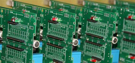
PCB (printed circuit board) assembly is the process of soldering or mounting electronic components onto a PCB. The PCB serves as the base that mechanically supports and electrically connects the components using conductive traces, pads, and other features. PCB assembly is a crucial step in electronics manufacturing that requires precision, attention to detail, and adherence to standards and best practices.
PCB assembly can be done manually for low-volume prototypes or by automated equipment for high-volume production. The key steps in PCB assembly include:
- Solder paste application
- Component placement
- Reflow soldering
- Inspection and testing
Being professional in PCB assembly means following proper procedures, using the right tools and materials, and delivering high-quality, reliable results. Let’s explore some tips and best practices for professional PCB assembly.
Planning and Preparation
Create Detailed Assembly Drawings
Before starting assembly, create clear, detailed drawings that show the exact placement and orientation of each component on the PCB. Include reference designators, polarity markers, and any special instructions. Use industry-standard symbols and notation.
Gather All Necessary Components
Make a bill of materials (BOM) listing all the required parts for the assembly. Verify that you have the correct components and quantities on hand before beginning. Check that the components meet the specifications in the design.
Ensure Workstation Readiness
Prepare your workspace for assembly. This includes:
- Ensuring proper lighting
- Gathering necessary tools (tweezers, soldering iron, etc.)
- Laying out components and materials for easy access
- Providing ventilation and ESD protection
Use Proper ESD Precautions
Electrostatic discharge (ESD) can damage sensitive electronic components. When handling PCBs and parts, always:
- Wear an ESD wrist strap connected to ground
- Use an ESD-safe mat on your work surface
- Store PCBs and components in ESD bags or containers
- Ground all tools and equipment

Solder Paste Application
Select the Right Solder Paste
Use solder paste that matches the alloy specified in the design, such as tin-lead or lead-free. Consider the paste’s particle size, flux activity, and viscosity for the application method (stencil printing, dispensing, etc.).
Prepare the Stencil
If using a solder paste stencil, ensure it is clean and free of damage. Inspect the apertures for proper sizing and alignment with the PCB pads. Secure the stencil to the PCB using a stencil frame or clips.
Apply Paste Properly
Apply solder paste to the PCB using the specified method (stencil printing, syringe dispensing, etc.). If stencil printing:
- Place the PCB and stencil in the printer
- Deposit paste on one end of the stencil
- Squeegee the paste across the stencil to fill apertures
- Carefully lift the PCB to release it from the stencil
Inspect the pasted PCB to ensure consistent, uniform paste deposits with no bridging or voids. Clean any excess or stray paste.
Control Paste Exposure
Solder paste is perishable and sensitive to air exposure. To maintain paste quality:
- Keep paste refrigerated when not in use
- Allow cold paste to reach room temperature before opening
- Re-seal paste containers promptly after use
- Discard expired or contaminated paste

Component Placement
Orient Components Correctly
Place components on the PCB in the correct locations and orientations per the assembly drawing. Pay attention to:
- Reference designator labels
- Pin 1 markers
- Polarity symbols (+ and -)
Some common component orientation conventions:
| Component | Placement |
|---|---|
| Resistors and capacitors | Either direction |
| Diodes | Band indicates cathode |
| ICs | Notch or dot indicates pin 1 |
| Polarized capacitors | Long lead indicates anode |
Align and Seat Components
Accurately align component leads or contacts with the PCB pads. Ensure leads are not bent or misaligned. Firmly seat the component against the PCB surface without applying excessive force. For through-hole parts, leads should protrude fully through the board.
Avoid Component Damage
Handle components carefully to avoid physical damage like bent leads or cracked packages. Do not expose parts to excess heat during soldering. Follow ESD precautions.

Reflow Soldering
Set Up the Reflow Oven
Program the reflow oven with the appropriate temperature profile for the solder paste and board/component thermal requirements. Typical lead-free profile:
| Phase | Temperature | Time |
|---|---|---|
| Preheat | 150-180°C | 60-120 sec |
| Soak | 150-200°C | 60-120 sec |
| Reflow | 230-250°C | 30-90 sec |
| Cooling | < 6°C/sec | – |
Ensure the oven is clean and functioning properly. Verify settings with a test run.
Position PCBs for Reflow
Place assembled PCBs on the oven conveyor or in pallets. Space boards evenly for consistent heating. Avoid overloading the oven, which can impede heat transfer.
Inspect Solder Joints
After reflow, carefully inspect solder joints for quality and completeness. Look for:
- Shiny, concave fillet shapes
- Wetting of component contacts and pads
- No bridging, voids, or excess solder
Rework or repair any defective solder joints.
Inspection and Testing
Visually Inspect the Assembly
Carefully examine the finished PCB assembly for:
- Correct component placement and orientation
- Good solder joint appearance
- Absence of damage or defects
Use magnification aids as needed to see small details.
Test Electrical Functionality
Perform electrical testing to verify that the assembled PCB functions properly. This may include:
- Powering up the board
- Checking for shorts or opens
- Measuring voltages and signals
- Running functional tests
Compare results to expected values from the design specifications. Debug and rework as needed.
Perform Quality Control Checks
Implement quality control processes to ensure consistent PCB assembly results. This can include:
- Visual inspection checklists
- Electrical test procedures
- Statistical process control (SPC) monitoring
- Traceability and record-keeping
Document and review quality data to identify trends and improvement opportunities.
Continuous Improvement
Monitor Process Metrics
Track key performance indicators (KPIs) for your PCB assembly process, such as:
- First-pass yield (FPY)
- Defects per million opportunities (DPMO)
- Cycle time
- On-time delivery
Use this data to set goals and measure progress.
Implement Best Practices
Follow industry standards and best practices for PCB assembly, such as:
- IPC-A-610 for workmanship
- J-STD-001 for soldering
- IPC-7711/7721 for rework and repair
Provide regular training to keep staff skills up to date.
Invest in Quality Tools and Equipment
Use high-quality, well-maintained tools and equipment for PCB assembly. This includes:
- Soldering irons and tips
- Solder paste printers
- Reflow ovens
- Inspection microscopes
- ESD protection gear
Upgrade or replace equipment as needed to stay current with technology advancements.
Foster a Culture of Quality
Instill a quality mindset throughout your organization. Encourage attention to detail, pride in workmanship, and a focus on customer satisfaction. Celebrate successes and learn from failures. Empower employees to identify and solve quality issues.
FAQ
What is the difference between surface mount and through-hole assembly?
Surface mount assembly involves soldering components directly onto PCB pads on the same side of the board. Through-hole assembly inserts component leads through holes in the PCB for soldering on the opposite side. Surface mount is more common for dense, compact designs, while through-hole is used for larger components or high-reliability applications.
How do I select the right solder paste?
Consider factors such as alloy type (tin-lead or lead-free), particle size, flux activity, and viscosity. Match the alloy to your process and the component/board metallization. Use finer particle sizes for smaller pitches. Select flux activity based on the oxidation levels of the surfaces to be soldered. Choose viscosity to suit your application method (printing, dispensing, etc.).
What causes solder bridges and how can I prevent them?
Solder bridges are unintended connections between adjacent pads or pins. They can be caused by excessive solder paste, improper stencil design, component misalignment, or incorrect reflow parameters. To prevent bridges, use a properly sized stencil, apply the right amount of paste, accurately place components, and optimize your reflow profile. Inspect for and clean any paste bridges before reflow.
How do I rework a defective solder joint?
First, identify the defective joint and determine the cause (insufficient solder, poor wetting, etc.). Clean the area of any residue or contamination. If needed, remove the component by heating the joint and gently prying it up. Clean the pads and component contacts. Re-apply solder paste if necessary. Place the component and re-solder using a heat source such as a soldering iron, hot air pencil, or reflow oven. Inspect the new joint for quality.
What are some common PCB assembly defects and how can I troubleshoot them?
Some common defects include:
- Solder bridges: Excessive solder shorting adjacent pads; fix by cleaning and resoldering
- Cold joints: Dull, grainy appearance from insufficient heat; fix by cleaning and resoldering with proper heat
- Tombstoning: Component stands up on one end due to uneven heating or pad sizing; fix by adjusting reflow or redesigning pads
- Insufficient solder: Starved or incomplete solder fillets; fix by adding more solder or paste
- Damaged components: Physical damage from improper handling; fix by replacing the component
Always inspect closely, identify the root cause, and take corrective action to prevent future occurrences.
Conclusion
Professional PCB assembly requires a combination of technical skills, attention to detail, and a commitment to quality. By following best practices for planning, component placement, soldering, inspection, and continuous improvement, you can consistently produce high-quality PCB assemblies that meet customer requirements and industry standards.
Remember to always prioritize safety, both for yourself and for the components and PCBs you are working with. Use the proper tools and equipment, follow ESD precautions, and maintain a clean, organized work environment.
As with any skill, PCB assembly proficiency comes with practice and experience. Don’t be discouraged by initial challenges or mistakes – instead, use them as opportunities to learn and improve. Stay current with industry developments and training, and never stop striving for excellence in your work.
By mastering the art and science of professional PCB assembly, you can build a successful career or business in the exciting field of electronics manufacturing. Happy soldering!


Leave a Reply