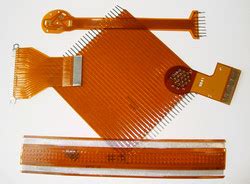
What are Flexible PCBs?
Flexible PCBs are printed circuit boards that are designed to be flexible and bendable, allowing them to conform to various shapes and fit into tight spaces. Unlike traditional rigid PCBs, which are made from a solid substrate material, flexible PCBs are constructed using thin, flexible materials such as polyimide or polyester films.
The basic structure of a flexible PCB consists of the following layers:
- Flexible substrate (e.g., polyimide or polyester)
- Conductive copper traces
- Cover layer (optional)
- Adhesive (optional)
Flexible PCBs can be single-sided, double-sided, or multi-layered, depending on the complexity of the circuit design and the application requirements.
Advantages of Flexible PCBs
Flexible PCBs offer several key advantages over traditional rigid PCBs:
-
Flexibility and Durability: The ability to bend and flex without breaking or losing functionality makes flexible PCBs ideal for applications that require movement, vibration resistance, or conformity to irregular shapes.
-
Compact Design: Flexible PCBs enable the creation of smaller, lighter, and more compact electronic devices by allowing the circuit to be folded or shaped to fit into tight spaces.
-
Reduced Assembly Costs: By eliminating the need for connectors and wires between different parts of a circuit, flexible PCBs can simplify the assembly process and reduce overall manufacturing costs.
-
Improved Signal Integrity: The shorter distances between components and the reduced number of connectors in flexible PCBs can lead to improved signal integrity and reduced electromagnetic interference (EMI).
-
Enhanced Reliability: Flexible PCBs are more resistant to vibration, shock, and thermal stress compared to rigid PCBs, resulting in improved reliability and longer product life.

Manufacturing Process of Flexible PCBs
The manufacturing process of flexible PCBs shares some similarities with that of rigid PCBs but also involves unique steps to achieve the desired flexibility and durability. The primary steps in the manufacturing process include:
-
Substrate Preparation: The flexible substrate material, such as polyimide or polyester, is cleaned and treated to ensure proper adhesion of the copper traces.
-
Copper Lamination: A thin layer of copper is laminated onto the substrate using heat and pressure.
-
Circuit Patterning: The desired circuit pattern is transferred onto the copper layer using photolithography, followed by etching to remove the unwanted copper.
-
Cover Layer Application (Optional): A cover layer, also known as a coverlay or solder mask, may be applied to protect the copper traces and provide insulation.
-
Lamination: If the flexible PCB is multi-layered, the individual layers are aligned and laminated together using heat and pressure.
-
Drilling and Cutting: Holes are drilled for through-hole components, and the flexible PCB is cut to its final shape using a laser or die-cutting process.
-
Surface Finishing: The exposed copper pads are finished with a surface treatment, such as ENIG (Electroless Nickel Immersion Gold) or OSP (Organic Solderability Preservative), to protect the copper and enhance solderability.
-
Quality Control: The finished flexible PCBs undergo thorough inspections and testing to ensure they meet the required specifications and performance standards.

Applications of Flexible PCBs
Flexible PCBs find applications in a wide range of industries and products where flexibility, durability, and compact designs are essential. Some common applications include:
-
Consumer Electronics: Flexible PCBs are used in smartphones, tablets, smartwatches, and other portable devices to enable slim and compact designs while providing reliable connectivity between components.
-
Medical Devices: Flexible PCBs are essential in medical devices such as wearable monitors, implantable sensors, and diagnostic equipment, where they must conform to the human body and withstand repeated movements.
-
Automotive Electronics: In vehicles, flexible PCBs are used in applications such as dashboard displays, steering wheel controls, and sensor systems, where they must withstand vibrations, temperature fluctuations, and harsh environmental conditions.
-
Aerospace and Defense: Flexible PCBs are crucial in aerospace and defense applications, such as satellites, aircraft, and military equipment, where they must operate reliably in extreme conditions and withstand high levels of shock and vibration.
-
Industrial Automation: Flexible PCBs are used in industrial automation systems, such as robotic arms, sensors, and control panels, where they must bend and flex to accommodate moving parts and tight spaces.

Designing Flexible PCBs
Designing flexible PCBs requires careful consideration of several factors to ensure optimal performance, reliability, and manufacturability. Some key aspects to consider when designing flexible PCBs include:
-
Material Selection: Choose the appropriate flexible substrate material based on the application requirements, such as temperature range, chemical resistance, and dielectric properties.
-
Bend Radius: Determine the minimum bend radius that the flexible PCB must achieve without causing damage or compromising the circuit’s functionality.
-
Copper Thickness: Select the appropriate copper thickness based on the current carrying requirements and the desired flexibility of the PCB.
-
Trace Width and Spacing: Design the copper traces with appropriate width and spacing to ensure proper current carrying capacity and to minimize signal interference.
-
Stiffener Placement: Incorporate stiffeners in areas where the flexible PCB needs to be reinforced or connected to other components, such as connectors or rigid PCBs.
-
Strain Relief: Include strain relief features, such as curved traces or additional flexible layers, to minimize stress on the copper traces during bending and flexing.
-
Assembly Considerations: Design the flexible PCB with assembly in mind, considering factors such as component placement, soldering techniques, and the use of ZIF (Zero Insertion Force) connectors.
Challenges and Limitations of Flexible PCBs
While flexible PCBs offer numerous benefits, they also present some challenges and limitations that must be considered:
-
Cost: Flexible PCBs are generally more expensive to manufacture compared to rigid PCBs due to the specialized materials, processes, and equipment required.
-
Limited Component Options: Not all electronic components are suitable for use on flexible PCBs, as they must be able to withstand the bending and flexing of the circuit.
-
Manufacturing Complexity: The manufacturing process for flexible PCBs is more complex and requires specialized equipment and expertise, which can lead to longer lead times and higher costs.
-
Thermal Management: Flexible PCBs have limited options for thermal management compared to rigid PCBs, as they cannot accommodate large heatsinks or cooling solutions.
-
Durability Limitations: While flexible PCBs are generally durable, repeated bending and flexing can eventually lead to fatigue and failure of the copper traces or other components.
Frequently Asked Questions (FAQ)
-
Q: Can flexible PCBs be repaired if damaged?
A: Repairing flexible PCBs can be challenging due to their delicate nature and the specialized materials used. In most cases, it is more cost-effective to replace a damaged flexible PCB rather than attempting a repair. -
Q: How do I choose the right flexible substrate material for my application?
A: The choice of flexible substrate material depends on factors such as the operating temperature range, chemical resistance, dielectric properties, and the required flexibility. Polyimide is a popular choice for its excellent thermal stability and mechanical properties, while polyester is often used for lower-cost applications. -
Q: Can flexible PCBs be used in high-temperature applications?
A: Yes, certain flexible substrate materials, such as polyimide, can withstand high temperatures up to 200°C or more. However, the specific temperature rating will depend on the material and the design of the flexible PCB. -
Q: How do I ensure the reliability of my flexible PCB design?
A: To ensure the reliability of your flexible PCB design, consider factors such as the minimum bend radius, copper thickness, trace width and spacing, and strain relief features. Conducting thorough testing and validation of your design under real-world conditions can also help identify and address potential issues. -
Q: Can flexible PCBs be combined with rigid PCBs in a single design?
A: Yes, flexible PCBs can be combined with rigid PCBs to create a rigid-flex PCB Assembly. This approach allows for the benefits of both flexible and rigid sections in a single circuit, enabling more complex and versatile designs.
Conclusion
Flexible PCBs have become an essential component in the electronics industry, enabling the creation of compact, durable, and reliable devices across a wide range of applications. By understanding the unique characteristics, manufacturing processes, and design considerations associated with flexible PCBs, engineers and designers can harness their potential to create innovative and high-performance electronic products.
As technology continues to advance and the demand for smaller, lighter, and more flexible electronic devices grows, the importance of flexible PCBs will only continue to increase. By staying informed about the latest developments and best practices in flexible PCB design and manufacturing, companies can remain competitive and deliver cutting-edge products that meet the evolving needs of their customers.


Leave a Reply