Introduction
In this article, we will guide you through the process of creating your own digital Arduino Ammeter. An ammeter is a device used to measure electric current in amperes (A) in a circuit. With the help of an Arduino board and a few other components, you can build a reliable and accurate ammeter for your projects. This DIY Arduino ammeter is a great tool for hobbyists, students, and professionals alike.
What is an Ammeter?
An ammeter is an electrical instrument that measures the current flowing through a circuit. It is connected in series with the circuit, allowing the current to pass through the meter. The ammeter displays the current value, typically in amperes (A) or milliamperes (mA).
Types of Ammeters
There are two main types of ammeters:
-
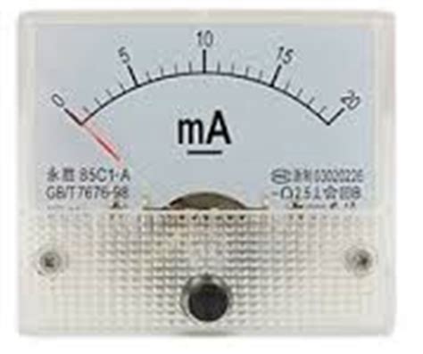
Analog Ammeters: These meters use a moving coil mechanism to display the current value on a scale. They are less precise than digital ammeters and can be affected by external factors such as magnetic fields.
-
Digital Ammeters: These meters use electronic components to measure and display the current value on a digital screen. They offer higher precision and are not affected by external factors.

Components Required
To build your Arduino ammeter, you will need the following components:
| Component | Quantity |
|---|---|
| Arduino Uno board | 1 |
| ACS712 current sensor module | 1 |
| LCD display (16×2) | 1 |
| 10kΩ potentiometer | 1 |
| Breadboard | 1 |
| Jumper wires | As needed |

Building the Arduino Ammeter
Step 1: Connect the ACS712 Current Sensor
- Connect the VCC pin of the ACS712 module to the 5V pin on the Arduino board.
- Connect the GND pin of the ACS712 module to the GND pin on the Arduino board.
- Connect the OUT pin of the ACS712 module to the A0 pin on the Arduino board.
Step 2: Connect the LCD Display
- Connect the VSS pin of the LCD to the GND pin on the Arduino board.
- Connect the VDD pin of the LCD to the 5V pin on the Arduino board.
- Connect the V0 pin of the LCD to the middle pin of the 10kΩ potentiometer.
- Connect one of the outer pins of the potentiometer to the GND pin on the Arduino board and the other outer pin to the 5V pin on the Arduino board.
- Connect the RS pin of the LCD to digital pin 12 on the Arduino board.
- Connect the RW pin of the LCD to the GND pin on the Arduino board.
- Connect the E pin of the LCD to digital pin 11 on the Arduino board.
- Connect pins D4, D5, D6, and D7 of the LCD to digital pins 5, 4, 3, and 2 on the Arduino board, respectively.
Step 3: Upload the Code
Copy the following code and upload it to your Arduino board using the Arduino IDE:
#include <LiquidCrystal.h>

const int rs = 12, en = 11, d4 = 5, d5 = 4, d6 = 3, d7 = 2;
LiquidCrystal lcd(rs, en, d4, d5, d6, d7);

const int sensorIn = A0;
int mVperAmp = 185; // use 100 for 20A Module and 66 for 30A Module
double Voltage = 0;
double VRMS = 0;
double AmpsRMS = 0;

void setup() {
  lcd.begin(16, 2);
  lcd.print("Arduino Ammeter");
}

void loop() {
  Voltage = getVPP();
  VRMS = (Voltage/2.0) *0.707;
  AmpsRMS = (VRMS * 1000)/mVperAmp;

  lcd.setCursor(0, 1);
  lcd.print(AmpsRMS);
  lcd.print(" Amps RMS");

  delay(500);
}

float getVPP()
{
  float result;
  int readValue;
  int maxValue = 0;
  int minValue = 1024;

   uint32_t start_time = millis();
   while((millis()-start_time) < 1000) //sample for 1 Sec
   {
       readValue = analogRead(sensorIn);
       if (readValue > maxValue)
       {
           maxValue = readValue;
       }
       if (readValue < minValue)
       {
           minValue = readValue;
       }
   }

   result = ((maxValue - minValue) * 5.0)/1024.0;

   return result;
}
Step 4: Test the Ammeter
- Connect a load (e.g., a small appliance or a light bulb) in series with the ACS712 module.
- Power on the Arduino board and the load.
- The LCD display should show the current value in amperes (A).

Calibrating the Ammeter
To ensure accurate readings, you may need to calibrate your Arduino ammeter. Follow these steps:
- Connect a known load with a known current rating in series with the ACS712 module.
- Note the current value displayed on the LCD.
- If the displayed value differs from the known current rating, adjust the
mVperAmpvalue in the code accordingly. - Repeat the process with different known loads to fine-tune the calibration.
Frequently Asked Questions (FAQ)
-
What is the maximum current that this Arduino ammeter can measure?
The maximum current depends on the ACS712 module used. The 20A module can measure up to 20A, while the 30A module can measure up to 30A. -
Can I use a different current sensor module?
Yes, you can use other current sensor modules compatible with the Arduino board. However, you may need to modify the code accordingly. -
How accurate is this Arduino ammeter?
The accuracy of the ammeter depends on the calibration and the quality of the components used. With proper calibration, you can achieve an accuracy of ±1%. -
Can I use this ammeter for measuring AC current?
Yes, this ammeter can measure both AC and DC current. However, for AC current, the code provided calculates the RMS (Root Mean Square) value. -
Can I modify the code to display the current value in milliamperes (mA)?
Yes, you can modify the code to display the current value in milliamperes by multiplying theAmpsRMSvalue by 1000 before displaying it on the LCD.
Conclusion
Building your own digital Arduino ammeter is a fun and educational project that can be completed in a few simple steps. With the help of an Arduino board, an ACS712 current sensor module, and an LCD display, you can create a reliable and accurate ammeter for measuring current in your circuits. This project is suitable for beginners and experienced makers alike, and it can be further customized and expanded to suit your specific needs.


Leave a Reply