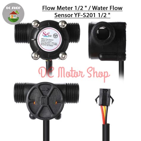
Introduction to the YF-s201 Water Sensor
The YF-s201 is a compact and versatile water flow sensor that consists of a plastic valve body, a water rotor, and a Hall Effect Sensor. As water flows through the valve, it causes the rotor to spin, and the Hall effect sensor detects the rotation, generating pulses that can be used to calculate the flow rate.
Key Features of the YF-s201 Water Sensor
- Accurate flow rate measurement
- Wide operating voltage range (5-24V DC)
- Easy integration with microcontrollers and development boards
- Compact and lightweight design
- Suitable for various pipe sizes (1/2″ to 1″)
YF-s201 Water Sensor Pinout and Wiring
The YF-s201 water sensor has three pins: VCC (power supply), GND (ground), and SIGNAL (pulse output). The pinout is as follows:
| Pin | Description |
|---|---|
| Red | VCC (5-24V DC) |
| Black | GND |
| Yellow | SIGNAL |
To use the YF-s201 water sensor with a microcontroller or development board, follow these wiring steps:
- Connect the red wire (VCC) to a power source between 5V and 24V DC.
- Connect the black wire (GND) to the ground pin of your microcontroller or development board.
- Connect the yellow wire (SIGNAL) to a digital input pin of your microcontroller or development board.
Wiring Diagram for Arduino
Here’s an example wiring diagram for connecting the YF-s201 water sensor to an Arduino board:
YF-s201     Arduino
-----------------------
VCC (Red)    5V
GND (Black)  GND
SIGNAL (Yellow)  Digital Pin 2

Measuring Flow Rate with the YF-s201 Water Sensor
The YF-s201 water sensor generates pulses as water flows through it. By counting these pulses over a specific time interval, you can calculate the flow rate. The sensor has a flow rate range of 1-30 L/min and a frequency range of 7.5-225 Hz.
Flow Rate Calculation Formula
To calculate the flow rate in liters per minute (L/min), use the following formula:
Flow Rate (L/min) = (Pulse Count / Pulse per Liter) / (Time Interval in Minutes)
The YF-s201 water sensor has a default pulse per liter value of 450, but this may vary depending on the specific model and calibration.
Example Arduino Code for Flow Rate Calculation
Here’s an example Arduino sketch that demonstrates how to measure the flow rate using the YF-s201 water sensor:
const int sensorPin = 2;
volatile int pulseCount = 0;
float flowRate;
unsigned long previousTime = 0;
const long interval = 1000; // 1 second

void setup() {
  pinMode(sensorPin, INPUT);
  attachInterrupt(digitalPinToInterrupt(sensorPin), pulseCounter, FALLING);
  Serial.begin(9600);
}

void loop() {
  unsigned long currentTime = millis();
  if (currentTime - previousTime >= interval) {
    detachInterrupt(digitalPinToInterrupt(sensorPin));
    flowRate = ((1000.0 / (currentTime - previousTime)) * pulseCount) / 450;
    Serial.print("Flow rate: ");
    Serial.print(flowRate);
    Serial.println(" L/min");
    pulseCount = 0;
    previousTime = currentTime;
    attachInterrupt(digitalPinToInterrupt(sensorPin), pulseCounter, FALLING);
  }
}

void pulseCounter() {
  pulseCount++;
}

Calibrating the YF-s201 Water Sensor
To ensure accurate flow rate measurements, it’s essential to calibrate the YF-s201 water sensor. The calibration process involves measuring the actual volume of water that passes through the sensor and comparing it with the calculated volume based on the pulse count.
Calibration Steps
- Connect the YF-s201 water sensor to your microcontroller or development board, as described in the wiring section.
- Upload a calibration sketch to your board that counts pulses over a fixed time interval (e.g., 1 minute).
- Place a measuring container at the outlet of the sensor and run water through the sensor for the fixed time interval.
- Record the pulse count and the actual volume of water collected in the container.
- Calculate the pulse per liter value using the following formula:
Pulse per Liter = Pulse Count / Actual Volume in Liters
- Update the pulse per liter value in your flow rate calculation code.

Applications of the YF-s201 Water Sensor
The YF-s201 water sensor is suitable for a wide range of applications, including:
- Smart home systems: Monitoring water usage and detecting leaks in pipes.
- Irrigation control: Measuring water flow to optimize irrigation schedules and conserve water.
- Industrial monitoring: Monitoring coolant flow in machines and detecting flow anomalies.
- Water treatment: Measuring the flow rate of water in filtration and purification systems.
- Aquariums and hydroponics: Monitoring water flow in aquariums and hydroponic systems.
Example Application: Smart Home Water Monitoring System
A smart home water monitoring system using the YF-s201 water sensor can help homeowners track their water usage and detect leaks early, saving water and preventing damage. Here’s a basic overview of how to implement such a system:
- Install YF-s201 water sensors on the main water supply line and individual appliance lines (e.g., washing machine, dishwasher).
- Connect the sensors to a microcontroller or development board, such as an Arduino or Raspberry Pi.
- Develop a program that reads the flow rate data from the sensors and sends it to a central hub or cloud platform.
- Create a user interface (e.g., mobile app or web dashboard) that displays water usage data and alerts users to potential leaks.
By continuously monitoring water flow and comparing it with historical data, the system can detect abnormal usage patterns and notify the homeowner, helping to conserve water and prevent costly damage.
Frequently Asked Questions (FAQ)
-
What is the maximum water pressure the YF-s201 water sensor can withstand?
The YF-s201 water sensor can withstand a maximum water pressure of 1.75 MPa (253.8 psi). -
Can the YF-s201 water sensor be used with hot water?
The YF-s201 water sensor is designed for use with cold water only. The maximum water temperature should not exceed 80°C (176°F). -
How accurate is the YF-s201 water sensor?
The accuracy of the YF-s201 water sensor is approximately ±10% when used within its specified flow rate range (1-30 L/min). However, accuracy can be improved through calibration. -
Can the YF-s201 water sensor be used with liquids other than water?
While the YF-s201 water sensor is primarily designed for use with water, it can be used with other non-corrosive liquids that have similar viscosity to water. However, the pulse per liter value may need to be adjusted for accurate flow rate measurements. -
How do I clean the YF-s201 water sensor?
To clean the YF-s201 water sensor, disconnect it from the power source and remove it from the pipe or tubing. Flush the sensor with clean water and use a soft brush to remove any debris from the rotor. Avoid using harsh chemicals or abrasive materials that may damage the sensor.
Conclusion
The YF-s201 Hall effect water sensor is a reliable and versatile tool for measuring water flow rate in various applications. Its ease of use, wide operating voltage range, and compatibility with popular microcontrollers and development boards make it an excellent choice for projects ranging from smart home systems to industrial monitoring.
By understanding the sensor’s pinout, wiring, and flow rate calculation process, you can effectively integrate the YF-s201 into your projects and develop innovative solutions for water management and conservation. With proper calibration and maintenance, the YF-s201 water sensor can provide accurate and consistent flow rate measurements, helping you optimize water usage and detect anomalies in your systems.


Leave a Reply