What is a Log Amplifier?
A log amplifier, short for logarithmic amplifier, is an electronic amplifier that produces an output signal that is proportional to the logarithm of the input signal. In other words, the voltage gain of a log amp decreases as the input signal increases. This non-linear behavior compresses the dynamic range of the input signal, allowing log amps to handle signals with a very wide dynamic range.
Log amplifiers have a variety of applications, including:
- Radar and sonar systems
- Audio and video compression
- Spectroscopy and scientific instrumentation
- Optical and RF power measurement
- Ultrasound and medical imaging systems
How Do Log Amplifiers Work?
The key component in a log amplifier is a non-linear element that has a logarithmic transfer function, such as a diode or transistor. When the input signal is applied to this non-linear element, it produces an output current that is proportional to the logarithm of the input voltage.
The basic concept can be understood by looking at the exponential I-V relationship of a diode:
$I = I_S (e^{V/nV_T} – 1)$
where:
– $I$ is the diode current
– $I_S$ is the reverse saturation current
– $V$ is the voltage across the diode
– $n$ is the ideality factor (typically between 1 and 2)
– $V_T$ is the thermal voltage (approximately 26 mV at room temperature)
When the diode is operating in the exponential region and $V >> nV_T$, the -1 term can be neglected and the equation can be simplified to:
$I ≈ I_S e^{V/nV_T}$
Taking the natural logarithm of both sides yields:
$\ln(I) ≈ \ln(I_S) + \frac{V}{nV_T}$
Solving for $V$:
$V ≈ nV_T \ln(\frac{I}{I_S})$
This shows that the voltage across the diode is proportional to the logarithm of the diode current. By using this logarithmic relationship, a log amplifier can compress the dynamic range of the input signal.
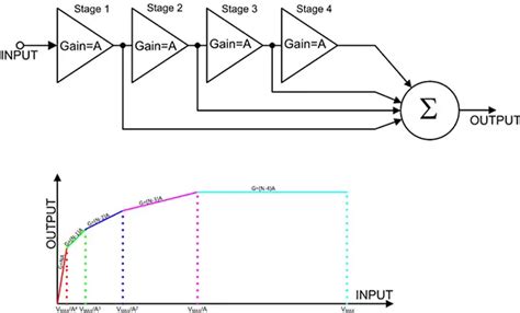
Successive Detection Log Amplifier
One common type of log amplifier is the successive detection log amplifier, also known as a cascade log amp or a piecewise linear log amp. This design consists of multiple gain stages, each with a linear amplifier and a detector. The detectors are typically diodes or transistors operating in their non-linear region.
The input signal is applied to the first gain stage, which amplifies the signal linearly. The output of this stage is then fed to the first detector, which produces an output current proportional to the logarithm of its input voltage. This current is summed with the currents from the other detectors and converted to an output voltage by a transimpedance amplifier.
As the input signal increases, it will eventually saturate the first gain stage and detector. At this point, the second gain stage takes over and provides additional amplification. This process continues through the cascade of gain stages and detectors, allowing the log amp to handle a wide dynamic range.
The output voltage of a successive detection log amp can be expressed as:
$V_{out} = V_Y \log_{10}(\frac{V_{in}}{V_X})$
where:
– $V_{out}$ is the output voltage
– $V_Y$ is the slope voltage, which determines the scaling of the output
– $V_{in}$ is the input voltage
– $V_X$ is the intercept voltage, which determines the input level at which the output is zero
The slope voltage $V_Y$ is typically around 25 mV per dB, while the intercept voltage $V_X$ depends on the design of the log amp and the desired input range.
True Log Amplifier
Another type of log amplifier is the true log amplifier, which uses a single non-linear element to achieve the logarithmic transfer function. This design typically employs a bipolar transistor operating in its exponential region.
The input signal is applied to the base of the transistor, while the collector current is held constant by a feedback loop. The emitter voltage of the transistor, which is proportional to the logarithm of the collector current, is buffered and used as the output of the log amp.
True log amplifiers have a wider dynamic range and better accuracy than successive detection log amps, but they are more complex and expensive to design and manufacture.

Key Specifications of Log Amplifiers
When selecting or designing a log amplifier, several key specifications must be considered:
Dynamic Range
The dynamic range of a log amp is the ratio of the largest to the smallest input signal that can be accurately processed. It is typically specified in decibels (dB) and can be calculated as:
$DR = 20 \log_{10}(\frac{V_{max}}{V_{min}})$
where:
– $DR$ is the dynamic range in dB
– $V_{max}$ is the maximum input voltage
– $V_{min}$ is the minimum input voltage
Log amplifiers can achieve dynamic ranges of 60 dB to 100 dB or more, depending on the design and the number of gain stages.
Bandwidth
The bandwidth of a log amp is the range of frequencies over which it can accurately process signals. It is typically specified as the -3 dB bandwidth, which is the range of frequencies where the output voltage is within 3 dB of its nominal value.
The bandwidth of a log amp is limited by the frequency response of the gain stages and detectors, as well as the settling time of the output stage. Wideband log amps can achieve bandwidths of several hundred MHz or more.
Accuracy
The accuracy of a log amp is a measure of how closely its transfer function matches an ideal logarithmic function. It is typically specified as the maximum deviation from the ideal function, in dB or percent.
The accuracy of a log amp is affected by factors such as temperature drift, supply voltage variation, and component tolerances. High-precision log amps can achieve accuracies of ±0.5 dB or better over their full dynamic range.
Slope and Intercept
The slope and intercept of a log amp’s transfer function determine how the output voltage scales with the input voltage. The slope is typically specified in mV/dB, while the intercept is specified as the input voltage at which the output is zero.
The slope and intercept can be adjusted by changing the values of certain components in the log amp circuit, such as resistors and diodes. This allows the log amp to be tailored to a specific application or input range.

Applications of Log Amplifiers
Log amplifiers are used in a wide range of applications where signals with a large dynamic range need to be processed. Some common applications include:
Radar and Sonar
In radar and sonar systems, log amps are used to compress the dynamic range of the received signals, which can vary by several orders of magnitude depending on the distance and reflectivity of the targets. By using a log amp, the signals can be more easily analyzed and displayed on a screen or recorded for further processing.
Audio and Video Compression
In audio and video compression systems, log amps are used to mimic the non-linear response of the human ear and eye. By compressing the dynamic range of the audio or video signal using a logarithmic function, the data can be more efficiently encoded and transmitted without sacrificing perceived quality.
Spectroscopy and Scientific Instrumentation
In spectroscopy and other scientific instruments, log amps are used to measure optical, RF, or acoustic power over a wide dynamic range. By using a log amp, the power levels can be accurately measured and displayed on a logarithmic scale, which is often more intuitive and useful than a linear scale.
Optical and RF Power Measurement
In optical and RF power measurement applications, log amps are used to convert the power of the signal into a voltage that can be easily measured and recorded. By using a log amp with a wide dynamic range, power levels from a few nanowatts to several watts can be accurately measured using the same instrument.
Ultrasound and Medical Imaging
In ultrasound and other medical imaging systems, log amps are used to compress the dynamic range of the received signals, which can vary by several orders of magnitude depending on the depth and acoustic properties of the tissue being imaged. By using a log amp, the signals can be more easily processed and displayed, allowing for clearer and more detailed images.

Designing a Log Amplifier
Designing a log amplifier requires careful consideration of the desired specifications, such as dynamic range, bandwidth, accuracy, and slope. The choice of the non-linear element, such as a diode or transistor, is critical to achieving the desired logarithmic transfer function.
Other important design considerations include:
- Bias circuits for the non-linear elements
- Feedback loops for stability and accuracy
- Temperature compensation circuits
- Bandwidth-limiting filters
- Output buffering and scaling circuits
Designing a high-performance log amp can be a complex and iterative process, often requiring simulation and prototyping to optimize the circuit for a specific application.
Calibration and Testing
Once a log amplifier has been designed and built, it must be carefully calibrated and tested to ensure that it meets the desired specifications. This typically involves:
- Measuring the transfer function over the full input range
- Checking the accuracy and linearity of the output
- Measuring the bandwidth and settling time
- Testing the temperature stability and supply voltage sensitivity
- Verifying the output scaling and intercept
Calibration may involve adjusting component values or bias currents to fine-tune the performance of the log amp. Testing should be performed under a range of operating conditions to ensure that the log amp will perform reliably in its intended application.
Advantages and Disadvantages of Log Amplifiers
Log amplifiers offer several advantages over linear amplifiers for certain applications:
- Wide dynamic range compression
- Logarithmic output scaling
- Insensitivity to input signal variations
- Simpler post-processing and display
However, log amplifiers also have some disadvantages:
- Non-linear transfer function
- Limited bandwidth compared to linear amplifiers
- More complex design and calibration
- Higher cost and power consumption
The choice between a log amp and a linear amp depends on the specific requirements of the application, such as the input signal range, the desired output format, and the post-processing needs.
FAQ
What is the difference between a log amp and a linear amp?
A log amp has a non-linear transfer function that compresses the dynamic range of the input signal, while a linear amp has a linear transfer function that preserves the dynamic range. Log amps are useful for applications where the input signal has a wide dynamic range and needs to be compressed for easier processing or display, while linear amps are better suited for applications where the input signal needs to be amplified without distortion.
What is the advantage of using a successive detection log amp over a true log amp?
Successive detection log amps are simpler and less expensive to design and manufacture than true log amps, because they use multiple gain stages and detectors to approximate the logarithmic transfer function. However, true log amps have a wider dynamic range and better accuracy, because they use a single non-linear element with a more precise logarithmic response.
How do I choose the right log amp for my application?
Choosing the right log amp depends on several factors, such as the input signal range, the desired output scaling and format, the bandwidth and settling time requirements, and the accuracy and temperature stability needed. It’s important to carefully evaluate the specifications of different log amps and consider the trade-offs between performance, complexity, and cost.
Can a log amp be used for AC signals?
Yes, a log amp can be used for AC signals, but the output will be a DC voltage that represents the logarithm of the envelope of the AC signal. To accurately process AC signals, the log amp must have a sufficiently wide bandwidth to capture the highest frequency components of the signal.
How do I calibrate a log amp?
Calibrating a log amp involves measuring its transfer function over the full input range and adjusting the component values or bias currents to achieve the desired slope, intercept, and accuracy. This typically requires specialized test equipment, such as a signal generator, power meter, and oscilloscope, as well as a thorough understanding of the log amp circuit and its operation. Many log amp manufacturers provide detailed calibration procedures and support to help users achieve the best performance from their devices.
Conclusion
Log amplifiers are a powerful tool for processing signals with a wide dynamic range, and they have many applications in fields such as radar, sonar, audio and video compression, spectroscopy, power measurement, and medical imaging. By using a non-linear element with a logarithmic transfer function, log amps can compress the dynamic range of the input signal and provide a logarithmic output that is easier to process and display.
Designing and calibrating a log amp requires careful consideration of the desired specifications and a thorough understanding of the circuit and its operation. However, the benefits of using a log amp, such as wide dynamic range compression and logarithmic output scaling, can be significant for many applications.
As technology continues to advance, log amplifiers are likely to find even more applications in areas such as wireless communications, high-speed data acquisition, and machine learning. By understanding the principles and applications of log amps, engineers and scientists can leverage this powerful tool to solve complex signal processing challenges and push the boundaries of what is possible.


Leave a Reply