Introduction to the TIP120 Transistor
The TIP120 is a popular NPN Darlington transistor widely used in electronics projects and applications. It is known for its high current gain, high power dissipation capability, and ease of use. In this article, we will cover the basics of the TIP120 transistor, its characteristics, applications, and provide helpful tips for using it effectively in your projects.
What is a Darlington Transistor?
Before diving into the specifics of the TIP120, let’s briefly discuss what a Darlington transistor is. A Darlington transistor is essentially two bipolar transistors connected in a cascaded configuration, where the emitter of the first transistor is connected to the base of the second transistor, and the collectors of both transistors are connected together. This configuration results in a high current gain, typically in the range of several thousand, making Darlington transistors suitable for applications that require high current amplification.
Key Features of the TIP120
The TIP120 transistor boasts several key features that make it a popular choice among electronics enthusiasts and professionals alike:
- High Current Gain: The TIP120 has a typical current gain (hFE) of 1000, allowing it to amplify small input currents into much larger output currents.
- High Collector Current: It can handle continuous collector currents up to 5A, making it suitable for driving high-current loads such as motors, relays, and high-power LEDs.
- High Power Dissipation: The TIP120 has a maximum power dissipation of 65W (at 25°C), enabling it to handle significant power levels without overheating.
- Wide Collector-Emitter Voltage Range: It can withstand collector-emitter voltages up to 60V, providing flexibility in circuit design.
- Integrated Flyback Diode: The TIP120 has a built-in flyback diode connected between the collector and emitter, which helps protect the transistor from voltage spikes caused by inductive loads.
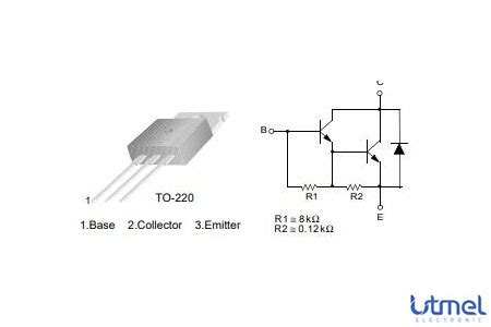
TIP120 Pinout and Package
The TIP120 transistor comes in a TO-220 package, which is a common package for power transistors. The TO-220 package has three pins: the base (B), collector (C), and emitter (E). The pinout of the TIP120 is as follows:
| Pin | Function |
|---|---|
| 1 | Base |
| 2 | Collector |
| 3 | Emitter |
It’s essential to identify the correct pins when connecting the TIP120 in a circuit to ensure proper operation and avoid damaging the transistor or other components.

Electrical Characteristics
To effectively use the TIP120 transistor in your projects, it’s crucial to understand its electrical characteristics. Here are some key parameters to consider:
| Parameter | Symbol | Value |
|---|---|---|
| Collector-Emitter Voltage | VCE(max) | 60V |
| Collector Current (Continuous) | IC(max) | 5A |
| Base Current (Continuous) | IB(max) | 120mA |
| Power Dissipation | PD(max) | 65W (at 25°C) |
| Current Gain (hFE) | hFE(min) | 1000 (typical) |
These values provide a guideline for operating the TIP120 within its safe limits. Exceeding these limits may lead to transistor damage or suboptimal performance.

TIP120 as a Switch
One of the most common applications of the TIP120 transistor is as a switch to control high-current loads. When used as a switch, the TIP120 operates in either the saturation region (fully on) or the cut-off region (fully off). By applying a sufficient base current, the transistor can be turned on, allowing current to flow from the collector to the emitter. When the base current is removed, the transistor turns off, blocking the current flow.
Here’s an example circuit that demonstrates the TIP120 used as a switch to control a motor:
           +---------------------+
           |                     |
           |                     |
           |         TIP120      |
           |        +---+        |
           |        |   |        |
           |        | B |        |
           |        |   |        |
           |      +-+   +--------+
           |      |      |       |
           |     / \    / \      |
           |     \ /    \ /      |
           |      |      |       |
           |     / \     |       |
           |     \ /     |       |
           |      |      |       |
           |      +-+    |       |
           |        |    |       |
           |        |   / \      |
           |        |   \ /      |
           |        |    |       |
           |        +-+  |       |
           |          |  |       |
           |         / \ |       |
           |         \ / |       |
           |          |  |       |
    +------+----------+  +-------+----+
    |                              |
    |                              |
+---+----+                     +---+----+
|  Motor |                     |  Power |
|        |                     | Supply |
+--------+                     +--------+
In this circuit, a microcontroller or other control signal is connected to the base of the TIP120 through a current-limiting resistor. When a high signal is applied to the base, the transistor turns on, allowing current to flow through the motor. When the base signal goes low, the transistor turns off, stopping the current flow and turning off the motor.

TIP120 as an Amplifier
While primarily used as a switch, the TIP120 can also be employed as an amplifier in certain applications. As a Darlington transistor, it provides high current gain, making it suitable for amplifying small input signals into larger output currents. However, due to its relatively low frequency response and high base-emitter voltage drop, the TIP120 is not ideal for high-frequency or precision amplification applications.
When using the TIP120 as an amplifier, it’s essential to properly bias the transistor and consider the maximum ratings to ensure stable and reliable operation. Proper heat dissipation is also crucial, as the TIP120 can generate significant heat when handling large currents.
Driving Inductive Loads with TIP120
Inductive loads, such as motors, solenoids, and relays, can present challenges when driven by transistors like the TIP120. When an inductive load is switched off, it generates a high-voltage spike known as back EMF (electromotive force), which can damage the transistor if not properly handled.
Fortunately, the TIP120 has a built-in flyback diode connected between the collector and emitter, which helps suppress these voltage spikes. The flyback diode provides a path for the inductive current to flow when the transistor is turned off, protecting the transistor from the back EMF.
However, in some cases, the built-in flyback diode may not be sufficient, especially for larger inductive loads or high-speed switching. In such situations, it’s recommended to add an external flyback diode in parallel with the inductive load to provide additional protection.
TIP120 Heat Dissipation and Thermal Management
Proper heat dissipation and thermal management are crucial when using the TIP120 transistor, especially in high-power applications. The TIP120 can generate significant heat when handling large currents, and if this heat is not effectively dissipated, it can lead to transistor damage or failure.
To ensure proper thermal management, consider the following guidelines:
- Use a heatsink: Attach a suitable heatsink to the TIP120 to help dissipate the generated heat. The size and type of heatsink depend on the power dissipation requirements of your application.
- Provide adequate ventilation: Ensure that there is sufficient airflow around the TIP120 and the heatsink to facilitate heat dissipation.
- Monitor the temperature: Use a temperature sensor or thermal monitoring circuit to keep track of the TIP120’s temperature during operation. If the temperature exceeds the maximum rating, take appropriate measures to reduce the power dissipation or improve the cooling.
- Use thermal compound: Apply a thin layer of thermal compound between the TIP120 and the heatsink to enhance heat transfer and improve thermal conductivity.
By following these guidelines, you can help ensure that the TIP120 operates within its safe temperature range and avoid thermal-related issues.
TIP120 Application Examples
The TIP120 transistor finds applications in a wide range of projects and circuits. Here are a few examples:
- Motor Control: Use the TIP120 to control the speed and direction of DC motors in robotics, automotive systems, and industrial automation.
- Relay Driver: Employ the TIP120 to drive relays, allowing low-current control signals to switch high-current loads.
- LED Driver: Control high-power LEDs or LED arrays using the TIP120, enabling brightness control and dimming.
- Solenoid Control: Use the TIP120 to control solenoids in automation systems, valves, and locking mechanisms.
- Audio Amplification: Utilize the TIP120 in low-frequency audio amplification circuits, such as simple speaker drivers or buzzer controls.
These are just a few examples of the many applications where the TIP120 transistor can be effectively used. Its versatility, high current handling capability, and ease of use make it a popular choice for a wide range of projects.
FAQ
1. What is the maximum collector current rating of the TIP120?
The TIP120 has a maximum continuous collector current rating of 5A.
2. Can I use the TIP120 without a heatsink?
While it is possible to use the TIP120 without a heatsink in low-power applications, it is generally recommended to use a heatsink to ensure proper heat dissipation and prevent transistor damage, especially when handling high currents.
3. Is the TIP120 suitable for high-frequency switching applications?
No, the TIP120 is not ideal for high-frequency switching applications due to its relatively low frequency response and high base-emitter voltage drop. It is better suited for low-frequency or DC switching applications.
4. Can I replace the TIP120 with another transistor?
When replacing the TIP120 with another transistor, ensure that the replacement transistor has similar or better specifications, such as the maximum collector-emitter voltage, maximum collector current, and power dissipation ratings. Also, consider the pinout compatibility and package type.
5. How do I choose the right base resistor value for the TIP120?
The base resistor value depends on the desired base current and the input signal voltage. Use Ohm’s law to calculate the resistor value: R = (Vin – Vbe) / Ib, where Vin is the input signal voltage, Vbe is the base-emitter voltage drop (typically around 2.5V for the TIP120), and Ib is the desired base current. Ensure that the base current is sufficient to saturate the transistor for proper switching operation.
Conclusion
The TIP120 transistor is a versatile and widely used NPN Darlington transistor that offers high current gain, high power dissipation capability, and ease of use. Its key features make it suitable for a wide range of applications, including motor control, relay driving, LED driving, and more.
When using the TIP120, it’s essential to understand its electrical characteristics, properly bias the transistor, and ensure adequate heat dissipation and thermal management. By following the guidelines and tips provided in this article, you can effectively incorporate the TIP120 into your projects and harness its capabilities.
Remember to always refer to the TIP120 datasheet for detailed specifications and operating conditions, and consult additional resources or seek expert advice when working with high-power or critical applications.
With its robustness and reliability, the TIP120 transistor remains a popular choice among electronics enthusiasts and professionals, offering a solid foundation for building powerful and efficient circuits.


Leave a Reply