1. Understand the Schematic
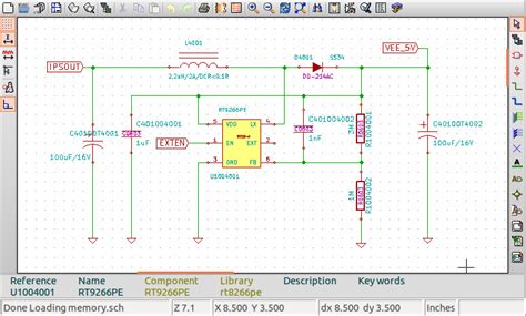
Before diving into the PCB layout process, it is crucial to thoroughly understand the schematic. Take the time to study the circuit diagram, identifying the various components, their connections, and the overall functionality of the design. Pay attention to the following aspects:
- Component specifications and ratings
- Power supply requirements
- Signal integrity concerns
- Grounding and shielding requirements
By gaining a deep understanding of the schematic, you can make informed decisions during the layout process and avoid potential issues down the line.
2. Choose the Right PCB Software
Selecting the appropriate PCB design software is essential for an efficient and effective layout process. Consider the following factors when choosing your PCB software:
- Ease of use and learning curve
- Compatibility with your schematic design tool
- Available libraries and component footprints
- Automation features and design rule checks (DRC)
- 3D visualization capabilities
- Manufacturability and output options
Some popular PCB design software options include:
| Software | Vendor | Key Features |
|---|---|---|
| Altium Designer | Altium | Comprehensive feature set, 3D visualization, strong community support |
| KiCad | KiCad EDA | Open-source, cross-platform, growing library and user base |
| Eagle | Autodesk | User-friendly interface, extensive component libraries, affordable |
| OrCAD | Cadence | Industry standard, robust simulation and analysis tools |
Choose a PCB software that aligns with your design requirements, budget, and skill level to streamline your workflow and achieve the best results.

3. Define the PCB Stackup
The PCB stackup refers to the arrangement of copper layers, dielectric materials, and planes within the PCB. Defining the appropriate stackup is crucial for signal integrity, power distribution, and manufacturability. Consider the following factors when defining your PCB stackup:
- Number of layers required based on design complexity
- Signal integrity requirements (e.g., controlled impedance)
- Power distribution and ground planes
- Dielectric material properties (e.g., FR-4, Rogers)
- Manufacturing capabilities and constraints
Work closely with your PCB manufacturer to determine the optimal stackup for your design, taking into account their manufacturing capabilities and any specific requirements your design may have.

4. Create a Component Placement Plan
Before placing components on the PCB, create a placement plan that considers the following aspects:
- Logical grouping of components based on functionality
- Minimizing the distance between connected components
- Placing sensitive components away from noise sources
- Accessibility for testing and debugging
- Mechanical constraints and enclosure requirements
A well-thought-out component placement plan can greatly simplify the routing process and improve the overall performance of your PCB.

5. Use a Consistent Grid System
Implementing a consistent grid system in your PCB layout can help maintain a clean and organized design. A grid system ensures that components and traces are aligned, making the layout more readable and easier to modify. Consider the following when setting up your grid system:
- Choose a grid size that accommodates your component footprints
- Align components and pads to the grid whenever possible
- Use a finer grid for dense areas and a coarser grid for less populated regions
- Maintain consistent spacing between components and traces
A consistent grid system not only improves the visual appeal of your PCB layout but also enhances manufacturability and reduces the likelihood of errors.
6. Route Power and Ground First
When routing your PCB, prioritize the power and ground connections. A robust power distribution network is essential for the proper functioning and reliability of your design. Consider the following tips when routing power and ground:
- Use wide traces or copper pours for power and ground connections
- Provide adequate copper coverage for power and ground planes
- Use multiple vias for power and ground connections to reduce inductance
- Place decoupling capacitors close to power pins of ICs
- Avoid running signal traces parallel to power traces to minimize crosstalk
By establishing a solid power distribution network early in the layout process, you can ensure stable voltage levels and minimize noise issues throughout your design.
7. Consider Signal Integrity
Signal integrity is a critical aspect of PCB layout, especially for high-speed designs. Poor signal integrity can lead to issues such as crosstalk, reflections, and electromagnetic interference (EMI). To maintain good signal integrity, consider the following tips:
- Route high-speed signals on dedicated layers
- Use controlled impedance traces for critical signals
- Minimize the length of high-speed traces
- Avoid sharp bends and use smooth curves for signal traces
- Provide adequate spacing between signal traces to reduce crosstalk
- Implement proper termination techniques (e.g., series termination, parallel termination)
By addressing signal integrity concerns during the layout process, you can ensure reliable communication between components and minimize the risk of signal degradation.
8. Optimize for Manufacturability
Designing a PCB layout that is optimized for manufacturability can save time, reduce costs, and improve the overall quality of your final product. Consider the following tips to enhance manufacturability:
- Adhere to the design rules and guidelines provided by your PCB manufacturer
- Use standard component footprints and sizes whenever possible
- Provide adequate clearance between components and traces
- Avoid using unnecessarily small trace widths and spacing
- Include fiducial markers and tooling holes for automated assembly
- Consider the soldermask and silkscreen requirements for your design
By collaborating closely with your PCB manufacturer and following their guidelines, you can ensure a smooth and efficient manufacturing process.
9. Perform Design Rule Checks (DRC)
Design rule checks (DRC) are automated checks performed by your PCB software to identify potential issues in your layout. Running DRC regularly throughout the layout process can help catch errors early and prevent costly redesigns. Common design rule checks include:
- Minimum trace width and spacing
- Pad and via size and spacing
- Copper to edge clearance
- Silkscreen to copper clearance
- Hole to hole spacing
Configure your DRC settings based on the manufacturing capabilities of your PCB fabricator and run checks frequently to ensure your design complies with the necessary rules and guidelines.
10. Review and Verify the Layout
Before finalizing your PCB layout, take the time to thoroughly review and verify the design. Involve other team members, such as electrical engineers and mechanical designers, to provide additional perspectives and catch any potential issues. Consider the following aspects during the review process:
- Component placement and orientation
- Trace routing and connectivity
- Power distribution and grounding
- Signal integrity and EMI considerations
- Mechanical fit and enclosure compatibility
- Manufacturability and assembly requirements
Use 3D visualization tools, if available, to check for any mechanical interferences or clearance issues. Generate and review manufacturing outputs, such as Gerber files and drill files, to ensure they meet the requirements of your PCB fabricator.
Frequently Asked Questions (FAQ)
1. What is the difference between a schematic and a PCB layout?
A schematic is a graphical representation of an electrical circuit, showing the components and their interconnections using standardized symbols. A PCB layout, on the other hand, is the physical representation of the circuit on a printed circuit board, specifying the placement of components and the routing of traces.
2. How do I choose the right PCB software for my project?
When choosing PCB software, consider factors such as ease of use, compatibility with your schematic design tool, available libraries and component footprints, automation features, and manufacturability options. Popular PCB software options include Altium Designer, KiCad, Eagle, and OrCAD. Select a software that aligns with your design requirements, budget, and skill level.
3. What is a PCB stackup, and why is it important?
A PCB stackup refers to the arrangement of copper layers, dielectric materials, and planes within a PCB. It is important because it directly affects signal integrity, power distribution, and manufacturability. The stackup determines the number of layers, the spacing between layers, and the properties of the dielectric materials used. Defining an appropriate stackup is crucial for ensuring the proper functioning and reliability of your PCB.
4. How can I improve signal integrity in my PCB layout?
To improve signal integrity in your PCB layout, consider the following tips:
– Route high-speed signals on dedicated layers
– Use controlled impedance traces for critical signals
– Minimize the length of high-speed traces
– Avoid sharp bends and use smooth curves for signal traces
– Provide adequate spacing between signal traces to reduce crosstalk
– Implement proper termination techniques (e.g., series termination, parallel termination)
5. What are design rule checks (DRC), and why are they important?
Design rule checks (DRC) are automated checks performed by PCB software to identify potential issues in your layout. They help ensure that your design complies with the manufacturing capabilities of your PCB fabricator and adhere to industry standards. Running DRC regularly throughout the layout process can help catch errors early, prevent costly redesigns, and improve the overall quality and manufacturability of your PCB.
Converting a schematic to a PCB layout requires careful planning, attention to detail, and consideration of various factors such as component placement, signal integrity, power distribution, and manufacturability. By following the 10 tips outlined in this article and regularly reviewing and verifying your design, you can create a PCB layout that meets your functional requirements, performs reliably, and is optimized for manufacturing. Remember to collaborate closely with your PCB manufacturer and adhere to their guidelines to ensure a smooth and successful transition from schematic to final product.


Leave a Reply