What is a Clapp Oscillator?
The Clapp oscillator, also known as the series-tuned Colpitts Oscillator, is a type of LC electronic oscillator that generates a sinusoidal output signal. It was invented in 1948 by James K. Clapp as a modification of the Colpitts oscillator design.
The Clapp oscillator is characterized by the use of a series LC circuit as its resonant tank circuit, with the feedback necessary for oscillation taken from a voltage divider made of two capacitors in series across the inductor.
Clapp Oscillator Circuit Diagram
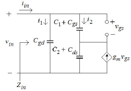
Here is the schematic diagram for a typical Clapp oscillator:
[Clapp oscillator circuit diagram]
The key components are:
- L1: Inductor in the LC tank circuit
- C1, C2: Capacitors forming the capacitive voltage divider
- C3: Additional series capacitor
- R1, R2: Biasing resistors
- RE: Emitter resistor
- CE: Bypass Capacitor
- Q1: Transistor (can be BJT or FET)
The transistor Q1 provides the gain and feedback necessary to sustain oscillations. The RF energy is coupled back to the emitter through capacitor C1. Resistors R1, R2, and RE establish the DC bias conditions. Capacitor CE is an emitter bypass capacitor.

How the Clapp Oscillator Works
The operation of the Clapp oscillator can be understood as follows:
-
The LC tank circuit, formed by L1 and C3 in series with the series combination of C1 and C2, determines the frequency of oscillation.
-
The voltage across C1 and C2 is a fraction of the total voltage across the tank circuit, providing positive feedback to the emitter of Q1.
-
Q1 amplifies this feedback signal, and the amplified signal appears again across the LC tank, maintaining the oscillations.
-
The oscillation frequency is determined primarily by the resonant frequency of the tank circuit, given by:
$$ f = \frac{1}{2\pi\sqrt{L_1C_T}} $$
where CT is the total capacitance in the tank circuit, given by:
$$ C_T = \frac{C_1C_2}{C_1+C_2} + C_3 $$
- The additional series capacitor C3 helps to improve frequency stability by reducing the effect of transistor capacitances.

Advantages of the Clapp Oscillator
The Clapp oscillator offers several advantages over other LC Oscillator topologies:
-
Improved frequency stability: The addition of the series capacitor C3 makes the Clapp oscillator less sensitive to variations in transistor parameters, resulting in better frequency stability.
-
Wide frequency range: By varying the values of L1, C1, C2, and C3, the Clapp oscillator can be designed to operate over a wide range of frequencies.
-
Good waveform purity: With proper design, the Clapp oscillator can produce a low-distortion sinusoidal output waveform.
-
Simple design: The Clapp oscillator requires relatively few components and is easy to design and construct.

Applications of the Clapp Oscillator
The Clapp oscillator finds use in a variety of electronic applications, including:
-
Radio transmitters and receivers: Clapp oscillators are often used as the local oscillator (LO) in radio transmitters and receivers to generate the carrier frequency or to provide frequency conversion.
-
Test and measurement equipment: Signal generators, frequency synthesizers, and other test and measurement instruments may use Clapp oscillators to generate stable, low-distortion test signals.
-
Wireless communication systems: In wireless communication systems, Clapp oscillators can be used to generate the carrier frequencies for modulation and demodulation.
-
Clock generation: Clapp oscillators can be used to generate clock signals for digital systems, providing a stable timebase for synchronous operations.
Designing a Clapp Oscillator
To design a Clapp oscillator for a specific frequency and application, follow these steps:
-
Choose the desired oscillation frequency and the inductor value L1. The inductor value is usually chosen based on practical considerations such as size and available standard values.
-
Calculate the total capacitance CT required for the desired frequency using the resonance equation:
$$ C_T = \frac{1}{(2\pi f)^2L_1} $$
-
Choose the values of C1, C2, and C3. As a starting point, make C1 and C2 equal and much larger than C3. A typical ratio is C1 = C2 = 10 × C3.
-
Calculate the actual values of C1, C2, and C3 based on the desired total capacitance CT:
$$ C_3 = \frac{C_T}{1 + \frac{C_T}{C_1+C_2}} $$
$$ C_1 = C_2 = \frac{C_T – C_3}{2} $$
-
Select the transistor Q1 based on the desired frequency, power output, and gain requirements. Ensure that the transistor has sufficient bandwidth and can handle the expected power dissipation.
-
Choose the bias resistors R1, R2, and RE to set the proper DC operating point for the transistor. The exact values will depend on the specific transistor and the desired performance characteristics.
-
Simulate the design using circuit simulation software to verify its performance and make any necessary adjustments.
-
Build a prototype and test it to confirm that it meets the design specifications.
Clapp Oscillator Design Example
Let’s design a Clapp oscillator with a frequency of 10 MHz using a 100 μH inductor. We’ll use a 2N3904 NPN transistor for Q1.
- Given:
- f = 10 MHz
-
L1 = 100 μH
-
Calculate CT:
$$ C_T = \frac{1}{(2\pi \times 10^7)^2 \times 100 \times 10^{-6}} = 25.3 \text{ pF} $$
- Choose C1, C2, and C3:
- Let C1 = C2 = 10 × C3
-
Assume C3 = 10 pF (a standard value)
-
Calculate actual values of C1 and C2:
$$ C_1 = C_2 = \frac{25.3 \text{ pF} – 10 \text{ pF}}{2} = 7.65 \text{ pF} $$
- Choose standard capacitor values close to the calculated values:
- C1 = C2 = 8.2 pF
-
C3 = 10 pF
-
Select bias resistors for the 2N3904 Transistor:
- R1 = 100 kΩ
- R2 = 47 kΩ
-
RE = 1 kΩ
-
Simulate the design and make adjustments as needed.
-
Build and test the prototype.
Here’s a table summarizing the component values for this design example:
| Component | Value |
|---|---|
| L1 | 100 μH |
| C1, C2 | 8.2 pF |
| C3 | 10 pF |
| R1 | 100 kΩ |
| R2 | 47 kΩ |
| RE | 1 kΩ |
| Q1 | 2N3904 |
Clapp Oscillator FAQ
-
What is the main difference between a Clapp oscillator and a Colpitts oscillator?
The main difference is the addition of a series capacitor (C3) in the Clapp oscillator, which is not present in the Colpitts oscillator. This extra capacitor helps to improve frequency stability by reducing the effect of transistor capacitances. -
Can a Clapp oscillator be used at high frequencies (e.g., above 100 MHz)?
Yes, Clapp oscillators can be designed to operate at high frequencies. However, at very high frequencies (above several hundred MHz), the Parasitic Capacitances and inductances of the components and circuit layout become more significant and can affect the oscillator’s performance. Careful design and layout techniques are required for high-frequency operation. -
What factors affect the frequency stability of a Clapp oscillator?
Several factors can affect the frequency stability of a Clapp oscillator, including: - Variations in the values of the LC tank components (L1, C1, C2, C3) due to temperature changes or aging
- Changes in the transistor parameters (e.g., capacitances, gain) due to temperature or voltage variations
- Variations in the supply voltage
-
Mechanical vibrations or shocks
To minimize these effects, use high-quality, stable components, regulate the supply voltage, and employ proper mechanical design and shielding. -
How can the output power of a Clapp oscillator be increased?
To increase the output power of a Clapp oscillator, you can: - Use a higher-power transistor for Q1
- Increase the supply voltage (within the limits of the transistor ratings)
- Use an impedance-matching network to efficiently couple the output signal to the load
-
Employ a buffer amplifier stage after the oscillator to increase the output power without loading the oscillator tank circuit
-
Can a Clapp oscillator be voltage-controlled for frequency modulation?
Yes, a Clapp oscillator can be voltage-controlled for frequency modulation by replacing one of the fixed capacitors (e.g., C3) with a varactor diode. The varactor diode’s capacitance varies with the applied voltage, allowing the oscillation frequency to be modulated by an external control voltage. This technique is often used in voltage-controlled oscillators (VCOs) for frequency synthesis and modulation applications.
In conclusion, the Clapp oscillator is a versatile and widely-used LC oscillator topology that offers good frequency stability, a wide frequency range, and low-distortion output. By understanding its principles, design considerations, and applications, you can effectively utilize Clapp oscillators in your electronic projects and systems.


Leave a Reply