Introduction to Voice Changer Circuits
A voice changer circuit, also known as a voice modulator circuit, is an electronic device that alters the pitch, frequency, or timbre of a person’s voice. These circuits are commonly used in various applications, such as voice disguisers, voice effects for music or entertainment, and even in communication systems for privacy and security purposes.
In this article, we will explore the fundamentals of voice changer circuits, their components, and how to build a simple voice modulator circuit using readily available electronic components.
Understanding the Basics of Voice Modulation
Voice modulation is the process of altering the characteristics of a voice signal to change its perceived sound. The human voice is essentially an acoustic wave generated by the vibration of the vocal cords. The pitch, or frequency, of the voice depends on the tension and length of the vocal cords, while the timbre, or quality, is determined by the shape and size of the vocal tract (throat, mouth, and nasal cavities).
To modulate a voice signal, we need to manipulate these characteristics electronically. This can be achieved through various techniques, such as:
- Frequency shifting: Shifting the frequency components of the voice signal up or down to change the perceived pitch.
- Amplitude modulation: Varying the amplitude of the voice signal to create a tremolo effect or to simulate a robotic voice.
- Filtering: Removing or emphasizing certain frequency bands to alter the timbre of the voice.

Components of a Voice Changer Circuit
A typical voice changer circuit consists of the following components:
- Microphone: Converts the acoustic voice signal into an electrical signal.
- Pre-amplifier: Amplifies the weak microphone signal to a suitable level for processing.
- Voice modulation stage: Applies the desired modulation techniques to the voice signal.
- Output amplifier: Amplifies the modulated signal to drive a speaker or headphones.
- Power supply: Provides the necessary voltage and current to the Circuit Components.

Building a Simple Voice Modulator Circuit
In this section, we will guide you through the process of building a simple voice modulator circuit using common electronic components. This circuit will employ frequency shifting to change the pitch of the voice.
Required Components
| Component | Quantity | Description |
|---|---|---|
| Electret Microphone | 1 | Converts acoustic voice signal to electrical signal |
| LM386 audio amplifier IC | 1 | Low-voltage audio power amplifier |
| NE555 timer IC | 1 | Generates a square wave for frequency shifting |
| 10 kΩ potentiometer | 1 | Adjusts the frequency of the square wave |
| 10 kΩ resistor | 2 | Used for biasing and setting gain |
| 1 kΩ resistor | 1 | Used for setting gain |
| 0.1 μF capacitor | 2 | Decoupling and filtering |
| 10 μF electrolytic capacitor | 2 | Decoupling and filtering |
| 100 μF electrolytic capacitor | 1 | Decoupling and filtering |
| 8 Ω speaker or headphones | 1 | Outputs the modulated voice signal |
| 9V battery | 1 | Powers the circuit |
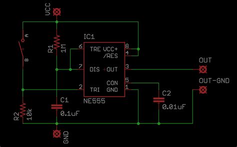
Circuit Diagram
[Insert a clear circuit diagram here, preferably created using a schematic capture software like KiCad or Eagle.]
Step-by-Step Assembly Instructions
- Connect the positive terminal of the electret microphone to the positive supply voltage through a 10 kΩ resistor, and the negative terminal to ground.
- Connect the output of the microphone to the non-inverting input (pin 3) of the LM386 audio amplifier IC.
- Connect a 10 kΩ potentiometer between pins 1 and 8 of the NE555 timer IC, with the wiper connected to pin 7.
- Connect a 0.1 μF capacitor between pins 6 and 7 of the NE555 timer IC.
- Connect the output (pin 3) of the NE555 timer IC to the inverting input (pin 2) of the LM386 audio amplifier IC through a 10 kΩ resistor.
- Connect a 1 kΩ resistor between pins 1 and 8 of the LM386 audio amplifier IC to set the gain.
- Connect the positive terminal of a 10 μF electrolytic capacitor to pin 5 of the LM386 audio amplifier IC, and the negative terminal to ground.
- Connect the positive terminal of a 100 μF electrolytic capacitor to pin 6 of the LM386 audio amplifier IC, and the negative terminal to the positive terminal of the 8 Ω speaker or headphones.
- Connect the negative terminal of the speaker or headphones to ground.
- Connect the positive terminal of the 9V battery to the positive supply voltage points of the circuit, and the negative terminal to ground.
Testing and Using the Voice Changer Circuit
- Ensure that all connections are secure and correctly placed.
- Connect the 9V battery to the circuit.
- Speak into the electret microphone and adjust the 10 kΩ potentiometer to change the pitch of your voice.
- The modulated voice will be heard through the connected speaker or headphones.

Customizing and Enhancing the Voice Changer Circuit
The simple voice modulator circuit described above can be customized and enhanced to achieve different voice effects and improve performance. Some possible modifications include:
- Adding a second NE555 timer IC to create a dual-pitch voice effect.
- Incorporating a low-pass, high-pass, or band-pass filter to emphasize or remove specific frequency ranges.
- Using a microcontroller or digital signal processor (DSP) to implement more advanced voice modulation techniques, such as vocoding or pitch correction.
- Improving the power supply filtering and regulation to reduce noise and ensure stable operation.
Applications of Voice Changer Circuits
Voice changer circuits have a wide range of applications, both for entertainment and practical purposes. Some common applications include:
- Voice disguisers for privacy and anonymity in communication systems.
- Voice effects for music production, live performances, and recording studios.
- Novelty toys and gadgets for children and adults.
- Assistive technology for individuals with speech impairments or disorders.
- Educational tools for teaching about acoustics, electronics, and signal processing.
Safety Considerations and Precautions
When building and using voice changer circuits, it is essential to follow proper safety guidelines to prevent accidents and ensure the longevity of the components. Some important considerations include:
- Always use a current-limiting resistor when connecting LEDs or other sensitive components to avoid overloading them.
- Ensure proper polarity when connecting electrolytic capacitors and other polarized components.
- Use heat sinks or cooling fans when working with high-power amplifiers or other components that generate significant heat.
- Avoid touching exposed electrical contacts or components while the circuit is powered on.
- Work in a well-ventilated area and avoid inhaling fumes when soldering components.
Conclusion
In this article, we have explored the fundamentals of voice changer circuits, their components, and how to build a simple voice modulator circuit using readily available electronic components. By understanding the basic principles of voice modulation and following the step-by-step assembly instructions, you can create your own voice changer circuit for various applications.
Remember to customize and enhance the circuit to achieve desired voice effects and always prioritize safety when working with electronics. With creativity and experimentation, you can unlock the full potential of voice changer circuits and explore new possibilities in voice modulation.
Frequently Asked Questions (FAQ)
-
Q: Can I use a different audio amplifier IC instead of the LM386?
A: Yes, you can use other audio amplifier ICs, such as the TDA2822M or the LM4871, as long as they are compatible with the voltage and power requirements of your circuit. -
Q: How can I make the voice changer circuit more compact and portable?
A: To make the circuit more compact and portable, you can use surface-mount components (SMD) instead of through-hole components, and design a custom printed circuit board (PCB) to minimize the overall size. -
Q: Can I use this voice changer circuit for professional audio applications?
A: While this simple voice changer circuit can be used for basic voice modulation, professional audio applications may require more advanced techniques and higher-quality components to achieve studio-grade results. -
Q: Is it possible to add a volume control to the voice changer circuit?
A: Yes, you can add a volume control by incorporating a potentiometer between the output of the LM386 audio amplifier IC and the speaker or headphones. -
Q: Can I power the voice changer circuit using a USB port instead of a 9V battery?
A: Yes, you can power the circuit using a USB port by using a voltage regulator, such as the LM7805, to step down the 5V USB voltage to the required voltage for your circuit components. However, ensure that the current drawn by your circuit does not exceed the maximum current rating of the USB port.


Leave a Reply