Introduction to the Mkr1000
The Mkr1000 is part of Arduino’s MKR family of boards, designed specifically for IoT applications. It is based on the Atmel ATSAMW25 SoC, which combines a SAMD21 Cortex-M0+ 32bit low power ARM MCU with a WINC1500 Wi-Fi module. This combination allows the Mkr1000 to offer a complete solution for IoT projects, with built-in Wi-Fi connectivity and a powerful microcontroller.
Key Features of the Mkr1000
- Atmel ATSAMW25 SoC (SAMD21 + WINC1500)
- 32-bit ARM Cortex M0+ processor
- 48 MHz clock speed
- 32 KB SRAM
- 256 KB Flash memory
- Built-in Wi-Fi 802.11 b/g/n connectivity
- Crypto-authentication hardware
- Operating voltage: 3.3V
- Digital I/O pins: 8
- PWM pins: 12 (0, 1, 2, 3, 4, 5, 6, 7, 8, 10, A3 – or 18 -, A4 -or 19)
- UART: 1
- SPI: 1
- I2C: 1
- Analog Input pins: 7 (ADC 8/10/12 bit)
- Analog Output pins: 1 (DAC 10 bit)
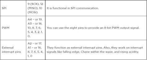
- External Interrupts: 8
- DC Current per I/O Pin: 7 mA
- Flash memory: 256 KB
- SRAM: 32 KB
- EEPROM: no
- Clock speed: 48 MHz
Mkr1000 Pinout
To effectively use the Mkr1000 in your projects, it is essential to understand its pinout and the functions of each pin. Let’s take a closer look at the Mkr1000 pinout diagram and the role of each pin.
Mkr1000 Pinout Diagram
[Include a clear, labeled image of the Mkr1000 pinout diagram]
Pin Descriptions
| Pin | Function | Details |
|---|---|---|
| VCC | Power Supply | 3.3V power supply input |
| GND | Ground | Common ground for the board |
| AREF | Analog Reference | Reference voltage for analog inputs |
| A0-A6 | Analog Inputs | 7 analog input pins, can also be used as digital I/O |
| 0-7 | Digital I/O | 8 digital input/output pins |
| 8, 10, A3(18), A4(19) | PWM Outputs | 4 additional PWM output pins |
| 11, 12 | SPI | SPI MOSI (11) and MISO (12) pins |
| 13 | SPI | SPI SCK pin |
| 14 | UART | UART TX pin |
| 15 | UART | UART RX pin |
| 16, 17 | I2C | I2C SDA (16) and SCL (17) pins |
| RST | Reset | Reset pin for the board |

Using the Mkr1000 in IoT Projects
Now that we have a better understanding of the Mkr1000 pinout, let’s explore how to use this board in IoT projects. We will cover setting up the development environment, connecting to Wi-Fi, and creating a simple IoT application.
Setting Up the Development Environment
-
Install the Arduino IDE: Download and install the latest version of the Arduino IDE from the official website (https://www.arduino.cc/en/software).
-
Add the Mkr1000 board to the Arduino IDE:
- Open the Arduino IDE
- Go to Tools > Board > Boards Manager
- Search for “Mkr1000” and install the “Arduino SAMD Boards (32-bits ARM Cortex-M0+)” package
-
Select the Mkr1000 board from Tools > Board > Arduino SAMD (32-bits ARM Cortex-M0+) > Arduino Mkr1000
-
Install the necessary libraries:
- Open the Arduino IDE
- Go to Sketch > Include Library > Manage Libraries
- Search for and install the following libraries:
- WiFi101
- ArduinoHttpClient
- Arduino_JSON
Connecting to Wi-Fi
To connect your Mkr1000 to a Wi-Fi network, follow these steps:
- Include the WiFi101 library in your sketch:
#include <WiFi101.h>
- Define your Wi-Fi network credentials:
char ssid[] = "your_wifi_ssid";
char pass[] = "your_wifi_password";
- In the
setup()function, initialize the Wi-Fi connection:
WiFi.begin(ssid, pass);
while (WiFi.status() != WL_CONNECTED) {
  delay(1000);
  Serial.println("Connecting to WiFi...");
}
Serial.println("Connected to WiFi");
Creating a Simple IoT Application
Let’s create a simple IoT application that sends temperature and humidity data to a remote server using the Mkr1000.
- Connect a DHT11 or DHT22 temperature and humidity sensor to your Mkr1000:
- VCC to 3.3V
- GND to GND
-
DATA to pin 2
-
Install the DHT library:
- Open the Arduino IDE
- Go to Sketch > Include Library > Manage Libraries
-
Search for “DHT” and install the “DHT sensor library” by Adafruit
-
Create a new sketch and include the necessary libraries:
#include <WiFi101.h>
#include <ArduinoHttpClient.h>
#include <DHT.h>
- Define your Wi-Fi credentials, server details, and DHT sensor:
char ssid[] = "your_wifi_ssid";
char pass[] = "your_wifi_password";
char serverAddress[] = "your_server_address";
int port = 80;

#define DHTPIN 2
#define DHTTYPE DHT11

DHT dht(DHTPIN, DHTTYPE);
- In the
setup()function, initialize the Wi-Fi connection and the DHT sensor:
void setup() {
  Serial.begin(9600);
  WiFi.begin(ssid, pass);
  while (WiFi.status() != WL_CONNECTED) {
    delay(1000);
    Serial.println("Connecting to WiFi...");
  }
  Serial.println("Connected to WiFi");

  dht.begin();
}
- In the
loop()function, read the temperature and humidity data from the DHT sensor and send it to the server:
void loop() {
  float temperature = dht.readTemperature();
  float humidity = dht.readHumidity();

  WiFiClient wifi;
  HttpClient client = HttpClient(wifi, serverAddress, port);

  String contentType = "application/x-www-form-urlencoded";
  String postData = "temperature=" + String(temperature) + "&humidity=" + String(humidity);

  client.post("/data", contentType, postData);

  delay(10000);
}
This example reads temperature and humidity data from the DHT sensor every 10 seconds and sends it to a server using an HTTP POST request.

FAQ
-
What is the difference between the Mkr1000 and other Arduino boards?
The Mkr1000 is specifically designed for IoT applications, with built-in Wi-Fi connectivity and a powerful Atmel ATSAMW25 SoC. It offers a compact form factor and low power consumption, making it ideal for battery-powered projects. -
Can I use the Mkr1000 with a 5V power supply?
No, the Mkr1000 operates at 3.3V and should not be connected to a 5V power supply. Doing so may damage the board. -
How do I update the firmware on my Mkr1000?
To update the firmware on your Mkr1000, follow these steps: - Connect your Mkr1000 to your computer via USB
- Open the Arduino IDE
- Go to Tools > Board > Arduino SAMD (32-bits ARM Cortex-M0+) > Arduino Mkr1000
-
Go to Tools > Burn Bootloader
-
Can I use the Mkr1000 with batteries?
Yes, the Mkr1000 can be powered using a 3.7V LiPo battery. You can connect the battery to the JST connector on the board. -
What is the range of the built-in Wi-Fi on the Mkr1000?
The range of the built-in Wi-Fi on the Mkr1000 depends on various factors, such as the environment and the antenna used. In ideal conditions, the Wi-Fi range can reach up to 100 meters.

Conclusion
The Arduino MKR1000 is a powerful and versatile board that is well-suited for IoT projects. Its built-in Wi-Fi connectivity, compact form factor, and low power consumption make it a preferred choice for developers looking to create connected devices quickly and easily. By understanding the Mkr1000 pinout and its features, you can effectively use this board in your IoT projects and bring your ideas to life.


Leave a Reply