Introduction to IC 4060
The IC 4060, also known as the CD4060 or MC14060, is a versatile 14-stage ripple carry binary counter and oscillator integrated circuit. This CMOS (Complementary Metal-Oxide-Semiconductor) device is widely used in various applications, such as frequency division, clock generation, and Timer Circuits. In this article, we will dive deep into the IC 4060 Pinout, its functions, and how to effectively utilize this component in your projects.
IC 4060 Pinout Diagram
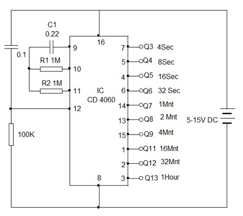
To understand the IC 4060 better, let’s start by examining its pinout diagram. The following table illustrates the pin configuration of the IC 4060 in a 16-pin DIP (Dual Inline Package) format:
| Pin Number | Pin Name | Description |
|---|---|---|
| 1 | Q13 | Output of the 13th stage |
| 2 | Q12 | Output of the 12th stage |
| 3 | Q11 | Output of the 11th stage |
| 4 | Q5 | Output of the 5th stage |
| 5 | Q4 | Output of the 4th stage |
| 6 | Q3 | Output of the 3rd stage |
| 7 | Q2 | Output of the 2nd stage |
| 8 | VSS | Ground (0V) |
| 9 | Q1 | Output of the 1st stage |
| 10 | RESET | Active-high reset input |
| 11 | Q9 | Output of the 9th stage |
| 12 | Q8 | Output of the 8th stage |
| 13 | Q10 | Output of the 10th stage |
| 14 | Q6 | Output of the 6th stage |
| 15 | Q7 | Output of the 7th stage |
| 16 | VDD | Positive supply voltage |
Understanding the Pin Functions
Now that we have an overview of the IC 4060 pinout, let’s explore the functions of each pin in detail.
Power Supply Pins (VDD and VSS)
- VDD (Pin 16): This pin is connected to the positive supply voltage, typically ranging from 3V to 15V, depending on the specific IC 4060 variant.
- VSS (Pin 8): This pin is connected to the ground (0V) of the circuit.
Output Pins (Q1 to Q13)
- Q1 to Q13 (Pins 1, 2, 3, 4, 5, 6, 7, 9, 11, 12, 13, 14, 15): These pins provide the output signals from the respective stages of the 14-stage ripple carry binary counter. Each output has a frequency that is half of the previous stage’s output.
Reset Pin (RESET)
- RESET (Pin 10): This active-high input pin is used to reset the counter to its initial state (all outputs low). When the RESET pin is pulled high, the counter is cleared, and the outputs remain low until the RESET pin is brought low again.

IC 4060 as an Oscillator
One of the key features of the IC 4060 is its ability to function as an oscillator. By connecting an external resistor (R) and capacitor (C) to the IC, you can generate a clock signal with a specific frequency. The oscillator frequency is determined by the values of R and C, and it can be calculated using the following formula:
f = 1 / (2.2 × R × C)
where:
– f is the oscillator frequency in Hz
– R is the resistance in ohms (Ω)
– C is the capacitance in farads (F)
To set up the IC 4060 as an oscillator, follow these steps:
1. Connect the external resistor between the RESET pin (Pin 10) and VDD (Pin 16).
2. Connect the external capacitor between the RESET pin (Pin 10) and VSS (Pin 8).
3. The oscillator output can be taken from any of the output pins (Q1 to Q13), depending on the desired frequency division.

Frequency Division with IC 4060
The IC 4060 is commonly used for frequency division applications. Each output pin (Q1 to Q13) provides a divided frequency of the oscillator signal. The division factor for each output pin is as follows:
| Output Pin | Division Factor |
|---|---|
| Q1 | 2 |
| Q2 | 4 |
| Q3 | 8 |
| Q4 | 16 |
| Q5 | 32 |
| Q6 | 64 |
| Q7 | 128 |
| Q8 | 256 |
| Q9 | 512 |
| Q10 | 1024 |
| Q11 | 2048 |
| Q12 | 4096 |
| Q13 | 8192 |
For example, if the oscillator frequency is 1 MHz, the output frequency at Q1 will be 500 kHz (1 MHz ÷ 2), and the output frequency at Q7 will be approximately 7.8 kHz (1 MHz ÷ 128).

Applications of IC 4060
The IC 4060 finds its place in a wide range of applications due to its versatility and ease of use. Some common applications include:
-
Frequency Division: As mentioned earlier, the IC 4060 is an excellent choice for dividing high-frequency signals into lower frequencies, making it suitable for various timing and control applications.
-
Clock Generation: By configuring the IC 4060 as an oscillator, you can generate clock signals with specific frequencies for use in microcontrollers, digital circuits, and other synchronous systems.
-
Timer Circuits: The IC 4060 can be used to create simple timer circuits by utilizing its frequency division capabilities. By selecting the appropriate output pin and external R-C values, you can achieve precise timing intervals.
-
Pulse Generation: The IC 4060 can generate pulses with specific widths and periods by combining its oscillator and frequency division features. This is useful in applications such as PWM (Pulse Width Modulation) control and signal conditioning.
-
Sequencing and Control: The multiple output stages of the IC 4060 can be used to create sequencing and control circuits. By logically combining the outputs, you can generate specific patterns or sequences for various applications, such as LED displays or motor control.
Tips for Using IC 4060
When working with the IC 4060, consider the following tips to ensure optimal performance and reliability:
-
Power Supply: Ensure that the power supply voltage (VDD) is within the specified range for your specific IC 4060 variant. Exceeding the maximum voltage rating can damage the device.
-
Decoupling Capacitors: To minimize noise and ensure stable operation, it is good practice to place decoupling capacitors (typically 0.1 µF) between VDD and VSS pins, as close to the IC as possible.
-
Reset Considerations: When using the RESET pin, ensure that it is pulled low during normal operation. A pull-down resistor can be used to prevent floating inputs and unwanted resets.
-
Output Loading: Be mindful of the output loading on each pin. The IC 4060 has a limited current sourcing and sinking capability. If driving high-current loads, consider using buffer stages or transistors to amplify the output current.
-
PCB Layout: Follow good PCB layout practices to minimize noise and crosstalk. Keep the traces for the oscillator components (R and C) as short as possible and route them away from high-frequency or noisy signals.
Frequently Asked Questions (FAQ)
-
Q: What is the maximum operating frequency of the IC 4060?
A: The maximum operating frequency of the IC 4060 depends on the specific variant and the supply voltage. Typically, it ranges from a few MHz to around 20 MHz. Consult the datasheet of your specific IC 4060 variant for accurate frequency specifications. -
Q: Can I use the IC 4060 with a crystal oscillator?
A: While the IC 4060 is primarily designed for use with an RC oscillator, it is possible to use it with a crystal oscillator. However, additional components, such as load capacitors and a feedback resistor, may be required to ensure proper oscillation. It is recommended to refer to the crystal oscillator’s datasheet and application notes for specific implementation details. -
Q: How do I select the appropriate values for the external resistor and capacitor for the oscillator?
A: The values of the external resistor (R) and capacitor (C) determine the oscillator frequency. Use the formula f = 1 / (2.2 × R × C) to calculate the required values. Choose R and C values that are within the recommended ranges specified in the IC 4060 datasheet. Typically, R values range from 10 kΩ to 1 MΩ, and C values range from 10 pF to 1 µF. -
Q: Can I use multiple output pins simultaneously for different frequency divisions?
A: Yes, you can use multiple output pins simultaneously to obtain different frequency divisions of the oscillator signal. Each output pin provides a divided frequency based on its division factor. Just ensure that the output loading and fan-out limitations are not exceeded. -
Q: Are there any alternative ICs similar to the IC 4060?
A: Yes, there are several alternative ICs that offer similar functionality to the IC 4060. Some examples include: - CD4020: 14-stage ripple carry binary counter
- CD4024: 7-stage ripple carry binary counter
- CD4040: 12-stage ripple carry binary counter
These ICs have different pin configurations and may offer additional features or variations in the number of counter stages.
Conclusion
The IC 4060 is a versatile and widely used integrated circuit that combines a 14-stage ripple carry binary counter and an oscillator. Its ability to generate divided frequencies and function as a clock source makes it suitable for a wide range of applications, including frequency division, timer circuits, and control systems.
By understanding the IC 4060 pinout and its functions, you can effectively utilize this component in your projects. Remember to consider factors such as power supply, output loading, and proper PCB layout to ensure optimal performance and reliability.
With its ease of use and flexibility, the IC 4060 is a valuable addition to any electronics engineer’s or hobbyist’s toolkit. Whether you are working on a simple timer circuit or a complex control system, the IC 4060 can provide the necessary frequency division and timing capabilities to bring your ideas to life.


Leave a Reply