What is a Breadboard?
A breadboard is a rectangular plastic board with a matrix of holes used for prototyping electronic circuits without soldering. It allows you to quickly and easily connect components to test and modify your circuit design before committing to a more permanent solution.
Anatomy of a Breadboard
A typical breadboard consists of the following parts:
- Terminal strips
- Power rails
- DIP support
- Tie-point matrix
Here is a diagram showing the parts of a breadboard:
| Terminal Strips | Power Rails | DIP Support | Tie-Point Matrix |
|---|---|---|---|
| Connect power | Distribute | Hold DIP | Connect |
| to rails | power to | chips | components |
| tie-points |
The terminal strips allow you to connect power to the power rails which run down the sides of the board. The DIP support in the middle holds DIP (dual in-line package) chips. The tie-point matrix makes up the main area where you connect components together.
How Breadboard Connections Work
Understanding Tie-Points
The tie-point matrix is made up of rows of electrically connected metal clips, typically in groups of 5 tie-points. Components plugged into the same row of 5 tie-points will be electrically connected.
For example, if you plug a wire into hole A1 and a LED into hole E1, they will be connected because A1-E1 are on the same row:
| A | B | C | D | E | |
|---|---|---|---|---|---|
| 1 | W | . | . | . | L |
W = wire
L = LED
. = empty tie-point
The A-E letters and 1-60 numbers help specify locations on the breadboard. Larger breadboards may have more rows and columns.
Power Rail Connections
The power rails down the sides are typically marked with red for positive voltage and blue/black for ground. They provide an easy way to distribute power to multiple components.
To connect power, you would:
- Connect a power source to the terminal strips
- Plug wires from the terminal strips into the power rails
- Use wires to connect from the power rails to component tie-points as needed
For instance, to power the LED from the previous example:
- Connect 5V to the (+) terminal strip
- Connect a wire from (+) terminal to (+) rail hole
- Connect a wire from (+) rail to a 330Ω resistor
- Connect resistor to D1 tiepoint
- Connect LED anode to E1 tiepoint
- Connect LED cathode to (-) rail
Here is a wiring diagram:
5V ─┬─ (+)rail─┬── 330Ω ──┬── LED ──┐
│ │ │ │
│ └── (-)rail ─────────┘
│
GND
Connecting Components
To connect components like resistors, capacitors, transistors, sensors, etc.:
- Determine what pins/legs need to be connected
- Plan out the placement on the tie-point matrix
- Plug the component legs into the appropriate tie-point holes
- Use wires to make connections between tie-point groups as needed
- Connect to power rails and terminal strips if required
Some tips:
– Avoid connecting power and ground to the same tie-point row
– Be mindful of current limitations, typically 1A per tie-point
– Use different color wires for organization, e.g. red for power
– Trim component legs if too long to avoid shorts
– Double-check connections before powering on

Common Breadboard Circuits
Here are some examples of useful circuits you can breadboard:
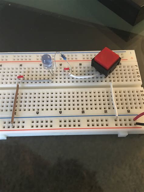
LED Circuit
A simple LED circuit requires an LED, current limiting resistor, and power source.
- Connect power to rails
- Connect resistor between rail and tie-point
- Connect LED anode to same tie-point as resistor
- Connect LED cathode to ground rail
Diagram:
330Ω LED
┌────┐ ┌───┐
│ │ │ │ A (+)
─┤ ├───┤ ├───── rail
│ │ │ │ K
└────┘ └─┬─┘
│
│ (-)
└────── rail
Transistor Switch
This uses a NPN transistor to control a higher current load.
- Connect load (motor, relay coil, etc) between power rail and collector
- Connect emitter to ground rail
- Connect resistors from base to signal and base to ground
Diagram:
┌── LOAD ───┐
(+) ──┤ │
│ │/ │
│ NPN │ │
│ │\ │
│ │ │
SIG ───┼─┬────┘ │
│ │ │
└─┴─ GND ────┘
555 Timer
The 555 timer IC is versatile for creating pulses, oscillators, and time delays. An astable configuration:
- Connect pin 1 (GND) to ground rail
- Connect pin 8 (VCC) to power rail
- Connect pins 2 and 6 together
- Connect timing resistor (RA) between pin 7 and power rail
- Connect timing resistor (RB) between pin 7 and pins 2/6
- Connect timing capacitor between pins 2/6 and ground rail
- Connect pin 3 (OUT) to output load
Diagram:
┌───────────────┐
RA │1 8│ │
┌──────┐│GND VCC │─────┴─ (+)
│ ││ │
│ 555││2 7│ │ RB
│ ││TRG DIS │──────┐
└──┬───┘│ │ │
│ │3 6│ │ │
└────┤OUT THR ├──────┘
│ │
OUT ──┤4 5│ │
│RST CONT│──┬───┐
└───────────┘ │ │
GND ──┴───┴─ C

FAQ
What is the difference between a solderless and solder breadboard?
A solderless breadboard uses friction to hold component legs in place for temporary prototyping. A solder breadboard has pads that you permanently solder components to for finished circuits.
Can I reuse a breadboard?
Yes, as long as the breadboard is not physically damaged and the tie-points still make good contact, you can reuse it indefinitely.
Are there any limitations to breadboarding?
Breadboards are not ideal for high-frequency circuits much above 10MHz due to capacitance and inductance effects. They are also limited in current handling to about 1A per tie-point. Soldered circuits are better for permanent installations.
How do I choose the right size breadboard?
That depends on the complexity of the circuit you want to build. For beginners, a standard 830 tie-point breadboard is a good size. Anything more complex may require a larger 1660 or 3220 tie-point breadboard. Very simple circuits can use a 270 or 400 tie-point mini breadboard.
What tools do I need to use a breadboard?
At minimum you need wire strippers and small pliers or tweezers to handle wires and components. A digital multimeter for measuring voltage, current, and continuity is highly recommended. A Variable Power Supply and oscilloscope are useful for more advanced electronics work.


Leave a Reply