What are Blocking Oscillators?
Blocking oscillators are a type of electronic oscillator circuit that generates a periodic output signal without the need for an external input signal. They are known for their simplicity, reliability, and ability to produce sharp, narrow pulses. Blocking oscillators find applications in various areas, such as pulse generation, timing circuits, and voltage conversion.
Key Characteristics of Blocking Oscillators
- Self-starting: Blocking oscillators can start oscillating on their own, without requiring an external trigger signal.
- Pulse generation: They are capable of generating sharp, narrow pulses with fast rise and fall times.
- Simplicity: Blocking oscillators have a relatively simple circuit design compared to other types of oscillators.
- Reliability: Due to their simplicity and self-starting capability, blocking oscillators are known for their reliability and robustness.
How do Blocking Oscillators Work?
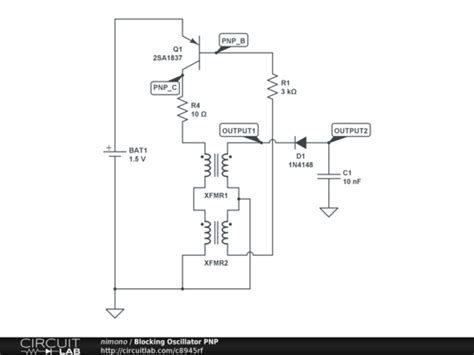
The working principle of a blocking oscillator revolves around the charging and discharging of a capacitor through a transformer. The basic components of a blocking oscillator circuit include:
- A transformer with a primary and secondary winding
- A capacitor connected across the primary winding
- A transistor or other active device (e.g., vacuum tube) connected to the primary winding
- A resistor connected to the base or grid of the active device
The Oscillation Cycle
- Initial state: When power is applied to the circuit, the capacitor is initially uncharged, and the transistor is in a non-conducting state.
- Capacitor charging: As the capacitor begins to charge through the primary winding of the transformer, it induces a voltage in the secondary winding.
- Transistor conduction: The induced voltage in the secondary winding is applied to the base or grid of the transistor, causing it to start conducting.
- Positive feedback: The conduction of the transistor causes a rapid increase in the current flowing through the primary winding, which further increases the induced voltage in the secondary winding. This positive feedback leads to a rapid buildup of current in the primary winding.
- Transformer saturation: As the current in the primary winding increases, the transformer core begins to saturate, leading to a decrease in the rate of change of the magnetic flux.
- Pulse generation: The decrease in the rate of change of the magnetic flux causes a reduction in the induced voltage in the secondary winding. This, in turn, reduces the base or grid voltage of the transistor, causing it to turn off abruptly. The result is a sharp, narrow pulse at the output of the blocking oscillator.
- Capacitor discharging: After the pulse is generated, the capacitor begins to discharge through the primary winding, and the cycle repeats itself.
The duration of the output pulse and the oscillation frequency are determined by the values of the capacitor, the transformer inductance, and the resistor connected to the active device.
Advantages of Blocking Oscillators
- Simple and compact circuit design
- Reliable and robust operation
- Capable of generating sharp, narrow pulses
- Wide range of output frequencies can be achieved by adjusting component values
- Low power consumption compared to other oscillator circuits
Disadvantages of Blocking Oscillators
- Limited frequency stability due to variations in component values and temperature
- Output pulse width and amplitude may vary with changes in load and supply voltage
- Difficulty in achieving precise control over the output pulse characteristics
- May generate electromagnetic interference (EMI) due to the sharp pulse edges

Types of Blocking Oscillators
There are two main types of blocking oscillators, differentiated by the configuration of the transformer windings and the active device used:
-
Common-Emitter (CE) Blocking Oscillator: In this configuration, the transformer’s primary winding is connected to the collector of the transistor, while the secondary winding is connected to the base. The emitter is connected to ground. CE blocking oscillators are known for their simplicity and ability to generate sharp, narrow pulses.
-
Common-Base (CB) Blocking Oscillator: In a CB blocking oscillator, the transformer’s primary winding is connected to the emitter of the transistor, while the secondary winding is connected to the base. The collector is connected to the power supply. CB blocking oscillators offer better frequency stability compared to CE configurations but have a lower gain.
Comparison of CE and CB Blocking Oscillators
| Characteristic | Common-Emitter (CE) | Common-Base (CB) |
|---|---|---|
| Circuit complexity | Simpler | Slightly more complex |
| Gain | Higher | Lower |
| Frequency stability | Lower | Higher |
| Pulse sharpness | Sharper | Less sharp |
| Pulse width control | Easier | More difficult |

Applications of Blocking Oscillators
Blocking oscillators find use in a wide range of electronic applications, including:
-
Pulse generation: Blocking oscillators are commonly used to generate sharp, narrow pulses for various purposes, such as triggering other circuits, driving displays, or creating timing signals.
-
Voltage conversion: By using a transformer with a suitable turns ratio, blocking oscillators can be used to step up or step down voltages. This is particularly useful in power supply circuits where a different voltage level is required.
-
Timing circuits: Blocking oscillators can be used as the basis for timing circuits, such as monostable multivibrators (one-shot circuits) or astable multivibrators (free-running oscillators).
-
Switching power supplies: In switching power supply designs, blocking oscillators can be used to generate the high-frequency switching signal required to control the power transistors.
-
Ignition systems: Blocking oscillators are used in the ignition systems of internal combustion engines to generate the high-voltage pulses required to fire the spark plugs.
-
Radar and sonar systems: The sharp, narrow pulses generated by blocking oscillators are useful in radar and sonar systems for transmitting and receiving signals.
-
CRT displays: In cathode-ray tube (CRT) displays, blocking oscillators are used to generate the high-voltage pulses required for the electron beam deflection and intensity control.

Design Considerations for Blocking Oscillators
When designing a blocking oscillator circuit, several factors need to be considered to achieve the desired performance:
-
Transformer Selection: The transformer is a critical component in a blocking oscillator circuit. The primary and secondary winding turns ratio, inductance, and core material must be carefully chosen to obtain the desired output pulse characteristics and frequency range.
-
Transistor selection: The choice of transistor depends on the desired output power, switching speed, and voltage/current ratings. High-frequency transistors with fast switching capabilities are often preferred for blocking oscillator applications.
-
Capacitor value: The capacitor connected across the primary winding of the transformer determines the pulse width and the oscillation frequency. A larger capacitor value results in a longer pulse width and a lower oscillation frequency, while a smaller capacitor value leads to shorter pulses and higher frequencies.
-
Base/grid resistor: The resistor connected to the base or grid of the transistor affects the oscillator’s starting characteristics and the output pulse shape. A lower resistance value provides a stronger positive feedback, resulting in faster starting and sharper pulses, but may also increase the power consumption and stress on the transistor.
-
Output load: The output load connected to the blocking oscillator can influence the output pulse shape and the oscillator’s stability. It is important to ensure that the load does not excessively dampen the oscillations or cause undesired reflections.
-
Electromagnetic compatibility (EMC): Due to the sharp pulse edges generated by blocking oscillators, they can be a source of electromagnetic interference (EMI). Proper circuit layout, shielding, and filtering techniques should be employed to minimize EMI and ensure compliance with relevant EMC standards.
Troubleshooting Blocking Oscillators
When working with blocking oscillators, some common issues may arise. Here are a few troubleshooting tips:
-
No oscillation: If the blocking oscillator fails to start oscillating, check the power supply connections, the transistor biasing, and the continuity of the transformer windings. Ensure that the transistor is properly connected and that the base/grid resistor value is appropriate for the transistor type.
-
Unstable oscillation: If the oscillator’s frequency or pulse characteristics are unstable, check the component values, especially the capacitor and the base/grid resistor. Ensure that the transformer core is not saturated and that the load is not excessively damping the oscillations. Consider adding a small capacitor across the base/grid resistor to improve stability.
-
Distorted output pulse: If the output pulse shape is distorted or has unwanted ringing, check the transistor’s switching characteristics and the transformer’s frequency response. Ensure that the transistor is not being driven beyond its rated limits and that the transformer is designed for the desired frequency range. Adding a small snubber network across the transformer’s primary winding may help reduce ringing.
-
Overheating: If the blocking oscillator circuit is overheating, check the power dissipation in the transistor and the transformer. Ensure that the component ratings are adequate for the application and that proper heat sinking is provided if necessary. Consider reducing the output power or the oscillation frequency to lower the power dissipation.
Frequently Asked Questions (FAQ)
-
What is the main difference between a blocking oscillator and other types of oscillators?
A blocking oscillator is distinguished by its ability to generate sharp, narrow pulses without the need for an external input signal. It relies on the charging and discharging of a capacitor through a transformer to produce the oscillations, whereas other oscillators may use different feedback mechanisms or resonant circuits. -
Can a blocking oscillator be used to generate sine waves?
No, blocking oscillators are not suitable for generating sine waves. They are primarily designed to produce sharp, narrow pulses with fast rise and fall times. For generating sine waves, other types of oscillators, such as LC Oscillators or Crystal Oscillators, are more appropriate. -
How can I change the output frequency of a blocking oscillator?
The output frequency of a blocking oscillator can be changed by adjusting the values of the capacitor connected across the primary winding of the transformer and the resistor connected to the base or grid of the transistor. Increasing the capacitor value or the resistor value will lower the oscillation frequency, while decreasing these values will increase the frequency. -
What is the purpose of the transformer in a blocking oscillator circuit?
The transformer in a blocking oscillator serves multiple purposes. It provides the necessary feedback to sustain the oscillations, couples the energy from the primary winding to the secondary winding to drive the transistor, and can also be used to step up or step down the output voltage if required. -
Are blocking oscillators still used in modern electronic circuits?
While blocking oscillators have been largely replaced by more advanced oscillator circuits in many modern applications, they still find use in certain niche areas where their simplicity, reliability, and ability to generate sharp pulses are advantageous. Examples include ignition systems, some power supply designs, and certain types of Sensor Circuits.
Conclusion
Blocking oscillators are a unique and valuable type of electronic oscillator circuit, known for their simplicity, reliability, and ability to generate sharp, narrow pulses. By understanding the working principles, types, and design considerations of blocking oscillators, engineers and hobbyists can effectively utilize them in a wide range of applications, from pulse generation and voltage conversion to timing circuits and power supplies.
While blocking oscillators may have limitations in terms of frequency stability and output pulse control compared to more advanced oscillator circuits, they continue to find use in specific applications where their characteristics are well-suited. As with any electronic design, careful component selection, circuit layout, and testing are essential to ensure optimal performance and reliability.
By exploring the fascinating world of blocking oscillators, one can gain a deeper appreciation for the elegance and versatility of these circuits and their role in the history and future of electronics.


Leave a Reply