Introduction to Potentiometer Wiring
A potentiometer is a three-terminal variable resistor commonly used in electronic circuits to control voltage, current, or other parameters. Proper wiring of a potentiometer is essential for its correct functioning and to ensure the desired control over the connected devices. In this article, we will dive deep into the process of potentiometer wiring, covering various aspects such as potentiometer types, wiring configurations, and practical applications.
Understanding Potentiometer Basics
What is a Potentiometer?
A potentiometer is a passive electronic component that acts as a variable resistor. It consists of a resistive element and a wiper that slides along the element, allowing the user to vary the resistance between the wiper and the end terminals. Potentiometers are used in a wide range of applications, including volume control, dimming lights, motor speed control, and sensor calibration.
Potentiometer Types
There are several types of potentiometers available, each with its own characteristics and suitability for different applications. The most common types include:
-
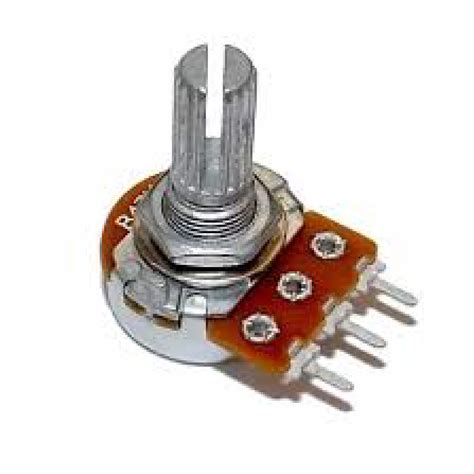
Rotary Potentiometers: These potentiometers have a circular resistive element and a rotating shaft that moves the wiper. They are commonly used in audio equipment, industrial controls, and user interfaces.
-
Slide Potentiometers: Slide potentiometers feature a linear resistive element and a sliding wiper. They are often used in audio mixers, lighting controls, and graphic equalizers.
-
Trimmer Potentiometers: Trimmer potentiometers are small, adjustable resistors used for fine-tuning and calibration. They are typically used in circuits requiring precise adjustments and are not intended for frequent user manipulation.
Potentiometer Specifications
When selecting a potentiometer for your project, consider the following specifications:
-
Resistance Range: Potentiometers are available in various resistance ranges, typically from a few ohms to several megohms. Choose a potentiometer with a resistance range suitable for your application.
-
Taper: The taper of a potentiometer refers to the relationship between the wiper position and the resistance change. Common tapers include linear (A), logarithmic (B), and anti-logarithmic (C). Select the appropriate taper based on your application requirements.
-
Power Rating: The power rating indicates the maximum power the potentiometer can dissipate without damage. Ensure that the potentiometer’s power rating is sufficient for your circuit.
-
Mechanical Characteristics: Consider the potentiometer’s mechanical aspects, such as shaft type, mounting style, and physical dimensions, to ensure compatibility with your project’s layout and enclosure.

Potentiometer Wiring Configurations
Basic Potentiometer Wiring
The most basic potentiometer wiring configuration involves connecting the potentiometer’s three terminals to the appropriate points in your circuit. The terminals are typically labeled as follows:
- Terminal 1: One end of the resistive element
- Terminal 2: The wiper (or slider)
- Terminal 3: The other end of the resistive element
To wire a potentiometer in this configuration:
- Connect terminal 1 to the positive supply voltage or the signal source.
- Connect terminal 3 to the ground or the negative supply voltage.
- Connect terminal 2 (the wiper) to the input of the device or circuit you want to control.
As you adjust the potentiometer, the wiper moves along the resistive element, varying the resistance between terminals 1 and 2, and terminals 2 and 3. This change in resistance allows you to control the voltage or current in your circuit.
Voltage Divider Configuration
Another common potentiometer wiring configuration is the voltage divider. In this setup, the potentiometer is used to create a variable voltage output by dividing the input voltage across the resistive element. To wire a potentiometer as a voltage divider:
- Connect terminal 1 to the positive supply voltage.
- Connect terminal 3 to the ground.
- Connect terminal 2 (the wiper) to the output of the voltage divider.
The output voltage at terminal 2 will vary between the supply voltage and ground, depending on the position of the wiper. This configuration is often used for adjusting reference voltages, controlling the brightness of LEDs, or setting the threshold for comparators.
Rheostat Configuration
In some cases, you may want to use a potentiometer as a variable resistor or rheostat. To achieve this, you need to use only two of the potentiometer’s terminals. There are two ways to wire a potentiometer as a rheostat:
- Two-terminal Rheostat:
- Connect terminal 1 to one end of your circuit.
- Connect terminal 2 (the wiper) to the other end of your circuit.
-
Leave terminal 3 unconnected.
-
Three-terminal Rheostat:
- Connect terminal 1 to one end of your circuit.
- Connect terminal 2 (the wiper) to terminal 3.
- Connect the joined terminals 2 and 3 to the other end of your circuit.
In both cases, adjusting the potentiometer will vary the resistance in your circuit, allowing you to control current flow or adjust the characteristics of connected components.

Potentiometer Wiring Considerations
When wiring potentiometers, keep the following considerations in mind:
Power Dissipation
Potentiometers have a maximum power rating that should not be exceeded. To calculate the power dissipation, use the formula: P = V^2 / R, where P is the power in watts, V is the voltage across the potentiometer, and R is the potentiometer’s total resistance. Ensure that the calculated power is within the potentiometer’s power rating to prevent damage.
Wiper Resistance
The wiper of a potentiometer has a small amount of resistance, typically a few ohms. This resistance can affect the accuracy of the potentiometer’s output, particularly in low-resistance circuits. If precision is critical, consider using a higher-quality potentiometer or implementing a buffer circuit to minimize the impact of wiper resistance.
Noise and Interference
Potentiometers can be susceptible to electrical noise and interference, especially in high-frequency applications. To minimize noise, use shielded cables for wiring and keep the potentiometer away from sources of electromagnetic interference. In some cases, adding a small capacitor across the potentiometer’s terminals can help filter out high-frequency noise.
Mechanical Wear
Potentiometers are subject to mechanical wear due to the constant movement of the wiper. Over time, the resistive element can become worn, leading to inconsistent or erratic behavior. If your application requires frequent adjustments, consider using a higher-quality potentiometer designed for extended use or implementing a digital control scheme using rotary encoders or digital potentiometers.

Potentiometer Wiring Examples
Example 1: Audio Volume Control
One common application of potentiometers is in audio volume control circuits. In this example, we’ll wire a potentiometer to control the volume of an audio signal.
- Connect terminal 1 of the potentiometer to the audio signal source (e.g., the output of an amplifier).
- Connect terminal 3 to the ground.
- Connect terminal 2 (the wiper) to the input of the next stage in the audio circuit (e.g., the input of a power amplifier).
As you rotate the potentiometer, the wiper moves along the resistive element, attenuating the audio signal and effectively controlling the volume.
Example 2: LED Dimmer
Potentiometers can also be used to control the brightness of LEDs. In this example, we’ll wire a potentiometer to dim an LED.
- Connect terminal 1 of the potentiometer to the positive supply voltage.
- Connect terminal 3 to one end of a Current-Limiting Resistor.
- Connect the other end of the current-limiting resistor to the anode (positive lead) of the LED.
- Connect the cathode (negative lead) of the LED to the ground.
- Connect terminal 2 (the wiper) of the potentiometer to the ground.
Adjusting the potentiometer will vary the voltage across the current-limiting resistor, controlling the current flow through the LED and, consequently, its brightness.
Example 3: Motor Speed Control
Potentiometers can be used in combination with motor drivers to control the speed of DC motors. In this example, we’ll wire a potentiometer to control the speed of a DC motor using an H-bridge motor driver.
- Connect terminal 1 of the potentiometer to the positive supply voltage.
- Connect terminal 3 to the ground.
- Connect terminal 2 (the wiper) to the speed control input of the H-bridge motor driver.
- Wire the H-bridge motor driver to the DC motor according to the manufacturer’s instructions.
As you adjust the potentiometer, the voltage at the speed control input of the H-bridge will vary, regulating the motor’s speed.
Troubleshooting Potentiometer Wiring
If you encounter issues with your potentiometer wiring, consider the following troubleshooting steps:
-
Check Connections: Ensure that all connections are secure and properly soldered. Loose or faulty connections can cause intermittent or erratic behavior.
-
Verify Wiring Configuration: Double-check your wiring against the intended configuration (e.g., basic wiring, voltage divider, or rheostat). Make sure the terminals are connected to the correct points in your circuit.
-
Test Continuity: Use a multimeter to test the continuity between the potentiometer’s terminals. An open circuit or high resistance may indicate a damaged potentiometer or broken wiper.
-
Measure Resistance: Measure the resistance between the potentiometer’s terminals using a multimeter. Verify that the resistance changes smoothly as you adjust the potentiometer and that the minimum and maximum resistance values match the potentiometer’s specifications.
-
Check Power Supply: Ensure that the potentiometer is receiving the correct supply voltage and that the voltage is stable. Fluctuations or inadequate voltage can affect the potentiometer’s performance.
-
Inspect for Physical Damage: Visually inspect the potentiometer for signs of physical damage, such as cracks, bent terminals, or a broken shaft. Replace the potentiometer if necessary.
-
Isolate the Problem: If the issue persists, try isolating the potentiometer by removing it from the circuit and testing it independently. This will help determine whether the problem lies with the potentiometer or other components in the circuit.
Potentiometer Wiring Safety Precautions
When working with potentiometers and electronic circuits, always prioritize safety. Follow these precautions to minimize the risk of injury or damage:
-
Disconnect Power: Before wiring or modifying a circuit, ensure that the power supply is disconnected to avoid electric shock or short circuits.
-
Use Appropriate Tools: Use the proper tools, such as wire strippers, soldering iron, and multimeter, to ensure safe and reliable connections.
-
Wear Protective Gear: When soldering or handling electronic components, wear safety glasses and protective gloves to shield yourself from potential hazards.
-
Avoid Overloading: Respect the potentiometer’s power rating and avoid exceeding it to prevent damage or overheating.
-
Insulate Connections: Use heat-shrink tubing or electrical tape to insulate exposed connections and prevent accidental short circuits.
-
Work in a Clean Environment: Maintain a clean and organized workspace to minimize the risk of accidents and ensure proper component handling.
Frequently Asked Questions (FAQ)
-
Q: Can I use a potentiometer to control AC voltage?
A: No, potentiometers are designed to work with DC voltage. Attempting to use a potentiometer with AC voltage can damage the component and pose safety risks. -
Q: How do I determine the appropriate potentiometer resistance for my circuit?
A: The appropriate potentiometer resistance depends on your specific application and the desired control range. Consider factors such as the supply voltage, the minimum and maximum desired output voltages, and the current requirements of the connected components. -
Q: Can I replace a failed potentiometer with one of a different resistance value?
A: It is generally not recommended to replace a potentiometer with one of a different resistance value unless you have carefully considered the impact on your circuit. Changing the resistance value can alter the control range and affect the performance of connected components. -
Q: How do I clean a dirty or oxidized potentiometer?
A: To clean a potentiometer, first, disconnect it from the circuit. Then, use a contact cleaner spray or a mixture of isopropyl alcohol and compressed air to clean the resistive element and the wiper. Allow the potentiometer to dry completely before reconnecting it to the circuit. -
Q: Can I use a multiturn potentiometer for more precise control?
A: Yes, multiturn potentiometers offer more precise control by allowing multiple rotations of the shaft to cover the full resistance range. They are ideal for applications requiring fine adjustments, such as calibration or sensor trimming.
Conclusion
Potentiometer wiring is a fundamental skill for anyone working with electronic circuits. By understanding the different potentiometer types, wiring configurations, and considerations, you can effectively incorporate potentiometers into your projects for smooth and reliable control. Remember to prioritize safety, follow best practices, and troubleshoot systematically if issues arise. With the knowledge gained from this article, you are well-equipped to tackle potentiometer wiring challenges and create innovative and functional electronic designs.


Leave a Reply