Introduction to Capacitive Voltage Dividers
A capacitive voltage divider is an electronic circuit that uses capacitors to divide an input voltage into a smaller output voltage. It works on the principle of capacitive reactance, which is the opposition to the flow of alternating current (AC) by a capacitor. Capacitive voltage dividers are widely used in various applications, such as signal conditioning, filtering, and impedance matching.
In this comprehensive guide, we will dive into the world of capacitive voltage dividers, exploring their working principles, design considerations, and practical applications. Whether you are an electronics enthusiast, a student, or a professional, this article will provide you with a solid understanding of capacitive voltage dividers and their role in electronic circuits.
How Capacitive Voltage Dividers Work
The Basics of Capacitors
To understand how capacitive voltage dividers work, let’s first recap the fundamentals of capacitors. A capacitor is a passive electronic component that stores electrical energy in an electric field. It consists of two conducting plates separated by an insulating material called a dielectric.
The capacitance of a capacitor is measured in farads (F) and is determined by the following formula:
C = ε × A / d
Where:
– C is the capacitance in farads (F)
– ε is the permittivity of the dielectric material
– A is the area of the conducting plates
– d is the distance between the plates
Capacitors have the ability to block direct current (DC) while allowing alternating current (AC) to pass through. This property makes them useful in various applications, such as filtering, coupling, and voltage division.
Capacitive Reactance
When an AC voltage is applied to a capacitor, it experiences capacitive reactance (Xc), which is the opposition to the flow of AC current. Capacitive reactance is measured in ohms (Ω) and is inversely proportional to the frequency of the applied AC voltage and the capacitance of the capacitor.
The formula for capacitive reactance is:
Xc = 1 / (2πfC)
Where:
– Xc is the capacitive reactance in ohms (Ω)
– f is the frequency of the AC voltage in hertz (Hz)
– C is the capacitance in farads (F)
From the formula, we can see that as the frequency increases, the capacitive reactance decreases, allowing more AC current to flow through the capacitor.
Voltage Division in a Capacitive Divider
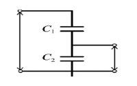
A capacitive voltage divider consists of two capacitors connected in series, as shown in the diagram below:
        +---||---+
Vin -----|  C1   |-----+----Vout
        +---||---+     |
                       |
        +---||---+     |
        |  C2   |-----+
        +---||---+
            |
            |
           GND
In this configuration, the input voltage (Vin) is applied across the series combination of capacitors C1 and C2. The output voltage (Vout) is taken across capacitor C2.
The voltage division in a capacitive divider is determined by the capacitive reactances of the capacitors. The output voltage can be calculated using the following formula:
Vout = Vin × [Xc2 / (Xc1 + Xc2)]
Where:
– Vout is the output voltage
– Vin is the input voltage
– Xc1 is the capacitive reactance of C1
– Xc2 is the capacitive reactance of C2
By selecting appropriate capacitance values for C1 and C2, we can achieve the desired voltage division ratio.

Designing Capacitive Voltage Dividers
Choosing the Right Capacitors
When designing a capacitive voltage divider, the choice of capacitors is crucial. Here are some factors to consider:
-
Capacitance Values: The capacitance values of C1 and C2 determine the voltage division ratio. It’s important to select capacitors with appropriate capacitance values to achieve the desired output voltage.
-
Voltage Rating: The capacitors used in the divider should have a voltage rating higher than the maximum expected input voltage to prevent damage and ensure reliable operation.
-
Tolerance: Capacitors have a tolerance rating that specifies the allowable variation in capacitance from the nominal value. Using capacitors with tighter tolerances will result in more accurate voltage division.
-
Temperature Coefficient: The capacitance of a capacitor can change with temperature. If the divider is expected to operate in a wide temperature range, it’s important to choose capacitors with low temperature coefficients to minimize variations in the output voltage.
-
Dielectric Material: Different dielectric materials offer various properties, such as stability, temperature range, and voltage handling capability. Common dielectric materials include ceramic, film, and electrolytic. Choose the appropriate dielectric material based on the application requirements.
Frequency Considerations
The frequency of the AC input voltage plays a significant role in the design of capacitive voltage dividers. As mentioned earlier, the capacitive reactance of a capacitor is inversely proportional to the frequency.
At low frequencies, the capacitive reactance is high, resulting in a larger voltage drop across the capacitors. As the frequency increases, the capacitive reactance decreases, allowing more AC current to flow through the divider.
When designing a capacitive voltage divider, it’s essential to consider the frequency range of operation and select capacitor values accordingly. The capacitor values should be chosen such that the capacitive reactances are much larger than the source and load impedances to ensure accurate voltage division.
Impedance Matching
Impedance matching is another important consideration in capacitive voltage divider design. The source impedance (Zs) and the load impedance (ZL) connected to the divider can affect the voltage division ratio and the overall performance of the circuit.
To minimize loading effects and ensure accurate voltage division, the impedance of the divider should be much higher than the load impedance. This can be achieved by selecting capacitor values that result in a high equivalent impedance of the divider.
The equivalent impedance of a capacitive voltage divider (Zeq) can be calculated using the following formula:
Zeq = Xc1 + Xc2
Where:
– Zeq is the equivalent impedance of the divider
– Xc1 is the capacitive reactance of C1
– Xc2 is the capacitive reactance of C2
By ensuring that Zeq is much larger than ZL, we can minimize the loading effect and maintain accurate voltage division.

Applications of Capacitive Voltage Dividers
Capacitive voltage dividers find applications in various areas of electronics. Let’s explore a few common applications:
Signal Conditioning
Capacitive voltage dividers are often used for signal conditioning purposes, such as attenuating high-voltage signals to levels suitable for measurement or further processing. By selecting appropriate capacitor values, we can reduce the amplitude of the input signal while preserving its waveform.
AC Coupling
Capacitive voltage dividers can be used for AC coupling, which involves removing the DC component of a signal while allowing the AC component to pass through. This is useful in applications where only the AC signal is of interest, such as in audio circuits or when connecting stages with different DC bias voltages.
Filtering
Capacitive voltage dividers can also act as simple high-pass filters. By choosing the capacitor values based on the desired cutoff frequency, we can attenuate low-frequency components of the input signal while allowing high-frequency components to pass through.
The cutoff frequency (fc) of a capacitive voltage divider can be calculated using the following formula:
fc = 1 / [2π(C1 + C2)R]
Where:
– fc is the cutoff frequency in hertz (Hz)
– C1 and C2 are the capacitance values in farads (F)
– R is the load resistance in ohms (Ω)
By adjusting the capacitor values and load resistance, we can design a capacitive voltage divider that acts as a high-pass filter with the desired cutoff frequency.
Impedance Matching in RF Circuits
Capacitive voltage dividers are commonly used for impedance matching in radio frequency (RF) circuits. By properly selecting the capacitor values, we can match the impedance of the source to the load, ensuring maximum power transfer and minimizing signal reflections.
In RF circuits, the characteristic impedance is typically 50 ohms. By designing a capacitive voltage divider with an equivalent impedance of 50 ohms, we can achieve impedance matching between the source and the load.

Practical Considerations and Limitations
While capacitive voltage dividers offer several advantages, there are some practical considerations and limitations to keep in mind:
-
Frequency Dependence: The voltage division ratio of a capacitive divider is frequency-dependent due to the variation in capacitive reactance with frequency. This means that the output voltage will vary with the frequency of the input signal.
-
Capacitor Tolerances: Capacitors have manufacturing tolerances that can affect the accuracy of the voltage division ratio. It’s important to consider the tolerances of the capacitors when designing the divider and to use capacitors with tight tolerances for critical applications.
-
Stray Capacitance: Stray capacitance, which is the unintended capacitance between conductors or components, can introduce errors in the voltage division ratio. Careful circuit layout and shielding techniques can help minimize the impact of stray capacitance.
-
Voltage Rating: Capacitors have a maximum voltage rating that should not be exceeded. When selecting capacitors for a voltage divider, ensure that they have an adequate voltage rating to handle the expected input voltage.
-
Power Dissipation: Capacitive voltage dividers are not suitable for high-power applications as capacitors have limited power handling capability. For high-power applications, resistive voltage dividers or other power-efficient techniques should be considered.
Frequently Asked Questions (FAQ)
-
What is a capacitive voltage divider?
A capacitive voltage divider is an electronic circuit that uses capacitors to divide an input voltage into a smaller output voltage. It works on the principle of capacitive reactance and is used in various applications such as signal conditioning, filtering, and impedance matching. -
How does a capacitive voltage divider work?
A capacitive voltage divider consists of two capacitors connected in series. The input voltage is applied across the series combination of the capacitors, and the output voltage is taken across one of the capacitors. The voltage division ratio is determined by the capacitive reactances of the capacitors. -
What factors should be considered when choosing capacitors for a voltage divider?
When choosing capacitors for a voltage divider, consider factors such as capacitance values, voltage rating, tolerance, temperature coefficient, and dielectric material. The capacitance values determine the voltage division ratio, while the other factors affect the accuracy, stability, and reliability of the divider. -
How does frequency affect a capacitive voltage divider?
The capacitive reactance of a capacitor is inversely proportional to the frequency of the applied AC voltage. As the frequency increases, the capacitive reactance decreases, allowing more AC current to flow through the divider. When designing a capacitive voltage divider, it’s important to consider the frequency range of operation and select capacitor values accordingly. -
What are some common applications of capacitive voltage dividers?
Capacitive voltage dividers find applications in signal conditioning, AC coupling, filtering, and impedance matching. They are used to attenuate high-voltage signals, remove DC components from AC signals, implement high-pass filters, and match impedances in RF circuits.
Conclusion
Capacitive voltage dividers are versatile and widely used circuits in electronics. By leveraging the principle of capacitive reactance, they allow us to divide an input voltage into a smaller output voltage. Understanding the working principles, design considerations, and practical applications of capacitive voltage dividers is essential for anyone involved in electronic circuit design.
In this comprehensive guide, we have explored the basics of capacitors, capacitive reactance, and voltage division in capacitive dividers. We have discussed the factors to consider when designing capacitive voltage dividers, such as choosing the right capacitors, frequency considerations, and impedance matching. We have also delved into the various applications of capacitive voltage dividers, including signal conditioning, AC coupling, filtering, and impedance matching in RF circuits.
By applying the knowledge gained from this guide, you can effectively design and utilize capacitive voltage dividers in your electronic projects. Whether you are working on signal processing, filtering, or impedance matching, capacitive voltage dividers provide a reliable and efficient solution.
Remember to consider the practical considerations and limitations, such as frequency dependence, capacitor tolerances, stray capacitance, voltage rating, and power dissipation, when implementing capacitive voltage dividers in your designs.
With a solid understanding of capacitive voltage dividers, you can unlock new possibilities in your electronic circuits and take your projects to the next level. Happy designing!


Leave a Reply