Introduction
Slotted holes are a common feature in mechanical engineering drawings, used to provide adjustability and allow for variations in part alignment during assembly. However, slotted holes are sometimes not depicted accurately on drawings, leading to slotted-hole discrepancies that can cause issues during manufacturing and assembly.
In this article, we’ll take an in-depth look at slotted holes, the common causes of slotted-hole discrepancies on drawings, the potential problems they can create, and best practices for avoiding them. We’ll also address some frequently asked questions about working with slotted holes.
What are Slotted Holes?
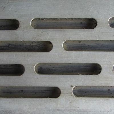
A slotted hole, also known as a slot or slotted opening, is an elongated hole cut into a part. Unlike a standard round hole, a slotted hole has a long oval shape. This provides some adjustability, allowing a bolt or other fastener to slide within the slot to account for variations in positioning.
Slotted holes are commonly used in applications such as:
- Adjustment of belt tension or chain sag
- Alignment of mating parts during assembly
- Accommodation of thermal expansion between parts
- Mounting of components that require positional calibration
The dimensions of a slotted hole are typically defined by the hole’s width (the diameter of the ends) and the length between the centers of the circular ends. The ends may also be specified using a radius.
| Dimension | Description |
|---|---|
| Width | The diameter of the circular ends of the slot |
| Length | The distance between the centers of the two circular ends |
| Radius | The radius of the circular ends (if specified this way) |

Types of Slotted Holes
There are a few different types of slotted holes that may be specified on an engineering drawing:
Plain Slotted Hole
A plain slotted hole is a simple slot with semi-circular ends. No special tolerances or controls are specified. The slot can be oriented horizontally, vertically, or at an angle as needed.
Controlled Radius Slotted Hole
In a controlled radius slotted hole, the radii at the ends of the slot are tightly controlled. This provides a more precise fit for the mating fastener. Controlled radius slots are often used when adjustability is needed but the assembly has tighter alignment tolerances.
Oversize Slotted Hole
An oversize slotted hole has larger end diameters than would normally be used for the fastener size. This provides a looser fit and greater adjustability. Oversize slots are used when significant position variation is expected.

Slotted Hole Dimensioning on Drawings
For a slotted hole to be manufactured correctly, it must be fully and accurately defined on the engineering drawing. The key dimensions that should be included are:
- Slot width (end diameter)
- Slot length (distance between end centers)
- Slot end radius (if controlled radius)
- Slot angle (if not parallel/perpendicular to part edges)
In addition, the drawing should specify:
- The surface in which the slot will be cut
- Any required tolerances on slot dimensions
- The number of slots and their positional pattern
The slot may be depicted in a partial or full section view if needed for clarity. Center lines are typically used to define the endpoints and centerline of the slot.

Common Slotted-Hole Discrepancies
There are several common ways in which the depiction of slotted holes on drawings can be inaccurate or incomplete, leading to discrepancies:
Incomplete Dimensioning
One of the most frequent discrepancies is a failure to fully dimension the slotted hole. Key dimensions such as the slot length or width may be missing. Without complete dimensions, the manufacturer has to make assumptions, potentially leading to slots that are the wrong size.
Tolerances Not Specified
Tolerances on slotted hole dimensions are often not specified on drawings. This can lead to problems if the slot is manufactured at the extreme end of the allowed dimensional variation, resulting in a slot that doesn’t provide the intended fit or adjustability. Tolerances should be specified where needed to ensure proper function.
Incorrect Hole Type
Sometimes a drawing will indicate a regular round hole where a slotted hole is actually needed. This can happen due to designer error or if the need for adjustability wasn’t considered. If manufactured as a regular hole, there will be no ability to make adjustments during assembly.
Ambiguous Slot Orientation
If the orientation of a slotted hole isn’t clearly defined relative to the part edges or datum features, it can be ambiguous. Machinists may cut the slot in the wrong direction. Slot angle should be clearly specified if the slot isn’t parallel or perpendicular to a part edge.
Conflicting Slot Definitions
Occasionally, the dimensions or specifications for a slotted hole may conflict between different views or sections of the drawing. For example, the slot length may be labeled differently on a top view vs. a section view. Conflicting information can cause confusion and lead to manufacturing errors.
Problems Caused by Slotted-Hole Discrepancies
Discrepancies in the way slotted holes are defined on drawings can lead to several manufacturing and assembly issues:
Incorrect Slot Size
If the slot dimensions are wrong or incomplete on the drawing, the slot may be manufactured at the wrong size. This can result in a slot that is too small to allow the needed adjustability or too large to securely hold the fastener.
Misaligned Slots
If the position or orientation of slotted holes is ambiguous on the drawing, they may be cut in the wrong location or direction. This can make it difficult or impossible to assemble mating parts. Misaligned slots can also interfere with proper fastener engagement.
Poor Fastener Fit
For a bolted joint to function properly, the fastener must have the right amount of engagement with the slotted hole. If the hole size isn’t correct or the radius at the slot ends is wrong, the fastener may fit too loosely or bind up in the slot.
Reduced Adjustability
The purpose of a slotted hole is usually to allow some adjustment between parts. But if the slot is the wrong size, in the wrong place, or oriented the wrong way because of drawing errors, that adjustability may be reduced or eliminated. This can make assembly difficult.
Scrap and Rework
If slotted holes aren’t made correctly due to drawing discrepancies, the parts may have to be scrapped or reworked. This wastes time and money. In some cases, the part may be unusable, impacting the overall production schedule.
Best Practices for Avoiding Slotted-Hole Discrepancies
To minimize the risk of slotted-hole discrepancies and ensure slotted holes are made correctly, follow these best practices:
Use CAD Software
Create engineering drawings using CAD (computer-aided design) software whenever possible. CAD programs can automatically dimension slots and flag missing dimensions. They also allow slots to be clearly defined in 3D space to avoid orientation and positioning errors.
Provide Complete Specifications
Always fully define each slotted hole on the drawing. Include all sizes, tolerances, and positioning data. Provide a clear datum reference for slot orientation. Use section views as needed to clearly show slot depth and position.
Include Tolerance Information
Don’t assume the machinist will know what tolerances to apply. Specify a tolerance for each slotted hole dimension on the drawing. Use a general tolerances block if the tolerances are the same for all slots. Tighter tolerances should be called out individually.
Seek Design Review
Have peers or managers review slotted hole designs and drawings to catch any errors or incomplete information. Design reviews are a good way to identify problems before release to manufacturing.
Use Standard Slotted Hole Sizes
Where possible, use standard slot end sizes that match standard fastener diameters. This makes the drawing clear and avoids confusion. If a custom size is needed, make sure it is fully defined with tolerances.
Communicate with Manufacturing
Work with the manufacturing team to understand any specific requirements they have for slotted hole drawing definitions. They may need information presented in a certain way. Drawings should always be clear to the end user.
Double Check Slot Orientation
It’s an easy mistake to draw a slotted hole at the wrong angle. Always double check that the orientation is clearly defined and correct. Pay attention to slots that aren’t horizontal or vertical.
Frequently Asked Questions
What is a slotted hole?
A slotted hole is an elongated hole in a part that allows the mating fastener to be adjusted within the length of the slot. This provides some positional flexibility during assembly.
How are the dimensions of a slotted hole specified?
The key dimensions for a slotted hole are the width (diameter of the slot ends), length (distance between slot end centers), and radius of the ends if it’s a controlled radius slot. The orientation angle is also important if the slot isn’t parallel to a part edge.
What problems can slotted-hole discrepancies cause?
Discrepancies in slotted hole drawings can lead to slots being made at the wrong size or in the wrong position. This can make assembly difficult, reduce adjustability, and potentially lead to scrap parts or rework.
How can I avoid slotted-hole discrepancies?
To avoid discrepancies, always fully define slotted holes on drawings, including dimensions, tolerances, and datums. Use CAD software to create drawings when possible. Have drawings reviewed to catch errors. Communicate with manufacturing to ensure drawing clarity.
What should I do if I find a Slotted-hole discrepancy?
If you identify a discrepancy on a drawing, mark it up and communicate the error to the engineering and manufacturing teams. Determine if parts already made from the drawing are usable. If the drawing is still in development, make the corrections before manufacturing starts.
Conclusion
Slotted-hole discrepancies on engineering drawings can lead to a range of manufacturing and assembly problems. Incorrect or missing dimensions, tolerances, and orientation data can result in slots being made the wrong size or in the wrong place. This reduces the adjustability slotted holes are intended to provide.
To avoid these costly problems, it’s important to always fully define slotted holes on drawings. Use CAD software to embed key information and reduce the risk of human error. Apply tolerances to slot dimensions. Get drawings reviewed for accuracy and clarity before release.
By following best practices and communicating clearly, engineers and machinists can work together to ensure slotted holes are depicted accurately and parts are made right the first time. Taking a little extra care in slotted hole design and drawing definition can prevent larger headaches down the road.


Leave a Reply