Introduction to ABS schematics
Anti-lock Braking Systems (ABS) are essential safety features in modern vehicles. They prevent the wheels from locking up during sudden or hard braking, allowing the driver to maintain steering control and reduce stopping distances. Understanding ABS schematics is crucial for automotive engineers, technicians, and enthusiasts to effectively design, maintain, and troubleshoot these systems.
Key Components of ABS
The main components of an ABS include:
- Wheel Speed Sensors
- ABS Control Module
- Hydraulic Valve Assembly
- Brake Master Cylinder
- Brake Fluid Reservoir
How ABS Works
When a driver applies the brakes forcefully, there is a risk of the wheels locking up, causing the vehicle to skid and lose steering control. ABS prevents this by rapidly adjusting the brake pressure on each wheel independently.
ABS Operation Cycle
The ABS operation cycle consists of three phases:
- Pressure Build-up: The brake pressure increases until the wheel is about to lock up.
- Pressure Hold: The brake pressure is held constant to prevent the wheel from locking.
- Pressure Release: The brake pressure is released to allow the wheel to regain traction.
This cycle is repeated multiple times per second until the vehicle comes to a stop or the driver releases the brake pedal.

ABS Schematic Diagrams
ABS schematic diagrams provide a visual representation of the system’s components and their interconnections. These diagrams are essential for understanding the system’s layout and troubleshooting issues.
Basic ABS Schematic
A basic ABS schematic includes the following components:
| Component | Function |
|---|---|
| Wheel Speed Sensors | Monitor the rotational speed of each wheel |
| ABS Control Module | Processes sensor data and controls the hydraulic valve assembly |
| Hydraulic Valve Assembly | Regulates brake fluid pressure to each wheel |
| Brake Master Cylinder | Generates initial brake fluid pressure |
| Brake Fluid Reservoir | Stores brake fluid for the system |
Advanced ABS Schematics
Advanced ABS schematics may include additional components and features, such as:
- Yaw Rate Sensors
- Lateral Acceleration Sensors
- Electronic Stability Control (ESC)
- Traction Control System (TCS)
These components work together to enhance vehicle stability and traction under various driving conditions.

ABS Wiring Diagrams
ABS wiring diagrams show the electrical connections between the system’s components. Understanding these diagrams is crucial for proper installation, maintenance, and troubleshooting of the ABS.
Wheel Speed Sensor Wiring
Each wheel speed sensor is connected to the ABS control module through a dedicated wiring harness. The wiring typically consists of a power supply, ground, and signal wires.
| Wire Color | Function |
|---|---|
| Red | Power Supply |
| Black | Ground |
| Yellow | Signal |
ABS Control Module Wiring
The ABS control module is the brain of the system, processing sensor data and controlling the hydraulic valve assembly. It is connected to various components through a complex wiring harness.
| Component | Wiring Connection |
|---|---|
| Wheel Speed Sensors | Signal, Power, Ground |
| Hydraulic Valve Assembly | Solenoid Control |
| Brake Light Switch | Power, Ground |
| Diagnostic Connector | Data Link Connector (DLC) |

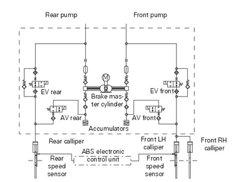
ABS Hydraulic Schematics
ABS hydraulic schematics show the layout and connections of the brake fluid lines and components. Understanding these schematics is essential for proper bleeding, maintenance, and troubleshooting of the ABS.
Hydraulic Valve Assembly
The hydraulic valve assembly consists of a series of solenoid valves that regulate brake fluid pressure to each wheel. The valves are controlled by the ABS control module based on sensor data.
| Valve | Function |
|---|---|
| Inlet Valve | Controls the flow of brake fluid from the master cylinder to the brake caliper |
| Outlet Valve | Controls the flow of brake fluid from the brake caliper to the reservoir |
Brake Fluid Flow
During normal braking, brake fluid flows from the master cylinder, through the inlet valves, to the brake calipers. When the ABS is activated, the hydraulic valve assembly rapidly opens and closes the inlet and outlet valves to regulate brake fluid pressure.
ABS Diagnostic and Troubleshooting
ABS diagnostic and troubleshooting involve using specialized tools and techniques to identify and resolve issues with the system. Common diagnostic methods include:
- Scanning for Diagnostic Trouble Codes (DTCs)
- Measuring wheel speed sensor signals
- Testing hydraulic valve resistance and operation
- Checking brake fluid level and condition
Common ABS Issues
Some common ABS issues include:
- Wheel speed sensor failure
- ABS control module malfunction
- Hydraulic valve stuck or leaking
- Low or contaminated brake fluid
- Wiring harness damage or corrosion
Regular maintenance and prompt attention to warning signs can help prevent and resolve ABS issues.
Frequently Asked Questions (FAQ)
-
What is the purpose of ABS?
ABS prevents wheel lockup during sudden or hard braking, allowing the driver to maintain steering control and reduce stopping distances. -
How does ABS work?
ABS rapidly adjusts brake pressure on each wheel independently by opening and closing solenoid valves in the hydraulic valve assembly. This process is controlled by the ABS control module based on wheel speed sensor data. -
What are the main components of ABS?
The main components of ABS are wheel speed sensors, ABS control module, hydraulic valve assembly, brake master cylinder, and brake fluid reservoir. -
How can I tell if my vehicle’s ABS is malfunctioning?
Common signs of ABS malfunction include the ABS warning light staying on, unusual brake pedal feel or response, and increased stopping distances. -
What should I do if I suspect an issue with my vehicle’s ABS?
If you suspect an issue with your vehicle’s ABS, have it inspected by a qualified automotive technician as soon as possible. They can diagnose the problem using specialized tools and perform the necessary repairs.
Conclusion
Understanding ABS schematics is crucial for automotive professionals and enthusiasts to effectively design, maintain, and troubleshoot these critical safety systems. By familiarizing yourself with the components, operation, and common issues of ABS, you can ensure optimal performance and safety of your vehicle’s braking system.


Leave a Reply