Introduction
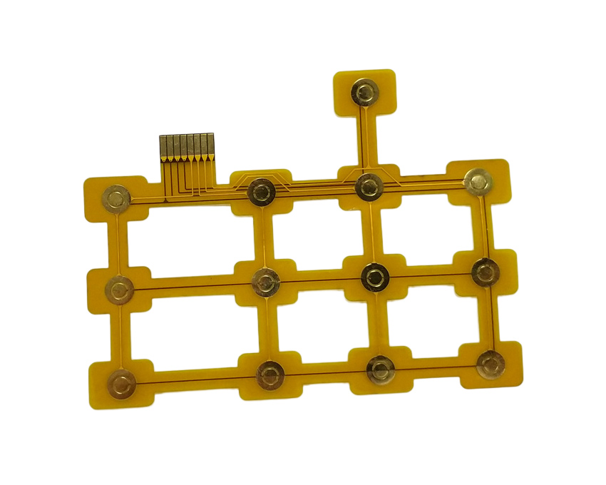
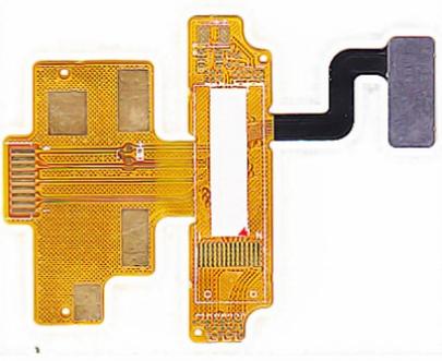
Flexible circuit boards, also known as flex circuits or flex PCBs, represent an exciting innovation in the field of electronics manufacturing. As their name suggests, these circuit boards are flexible and bendable, unlike traditional rigid circuit boards. This flexibility allows them to be designed into a huge range of shapes and configurations, enabling innovative and compact product designs across industries like consumer electronics, automotive, aerospace, medical devices and more.
In recent years, flexible circuit boards have seen tremendous growth thanks to their many advantages over rigid boards. Some of the key benefits offered by flex circuits include:
Lightweight and Thin Design
Flexible circuit boards are extremely lightweight and thin. This allows for integrated circuit packaging solutions that would not be possible with rigid boards. Products can be made lighter, thinner and more compact.
Increased Reliability
The flexible material used in flex circuits is resistant to cracking and fracturing from repeated bending and vibration stresses. This makes them ideal for dynamic applications.
Design Freedom and Flexibility
Flexible circuits allow for greater freedom of design compared to rigid boards. They can be bent, folded and configured to fit product requirements. Complex 3D stacking and wrapping around components is possible.
Higher Circuit Density
More circuits and components can be fit into a given area on a flex circuit versus a rigid board. Greater complexity and functionality can be achieved in a smaller footprint.
Improved Signal Integrity
The closely spaced traces and thin substrate used in flex circuits allow for shorter transmission lines and lower noise. This improves signal quality and performance.
Cost Effectiveness
By combining multiple rigid boards into a single flex assembly, costs can be reduced through lower part quantities, assembly time and points of failure.
This article provides an in-depth look at flexible circuit boards, their unique properties, how they are manufactured and the types of applications they enable across industries.
What Are Flex Circuits Made Of?

Flexible printed circuits are made up of three basic components:
Flexible Substrate Material
This forms the base of the circuit board. The most common materials used are polyimide or polyester films ranging from 12.5 to 100 micrometers thick. These provide the needed flexibility as well as electrical insulation and high temperature resistance.
Conductive Traces
The conducting paths or traces of the circuit are bonded onto the substrate. Copper is most commonly used due to its high conductivity and flexibility. Other materials like gold, nickel and silver can also be plated onto copper for oxidation resistance or solderability.
Coverlay/ Bonding Material
Coverlay, or overlay, refers to the insulating material laminated or bonded over the conductive traces for protection. Common materials include acrylic, polyimide and epoxy-based films. Bonding adhesives like acrylic or epoxy glue are used to attach coverlay.
By changing the properties and thicknesses of these constituent materials, flex circuits can be engineered with the specific mechanical, electrical and thermal characteristics needed by an application.
Flexible Circuit Board Construction
There are three common constructions used to make flexible circuit boards:
Single-Sided Flex Circuits
This is the simplest design with conductive traces patterned on just one side of the flexible substrate. Vias or plated through holes are used to cross traces between layers. Single-sided flex PCBs can be designed with or without coverlay. They are low cost and offer flexibility for simple applications.
Double-Sided Flex Circuits
In this construction, conductive traces are patterned on both sides of the substrate. This effectively doubles the circuit density. Vias allow connections between the two sides. Coverlay is commonly added to both sides to prevent shorting. Double-sided flex boards provide increased complexity in a small space.
Multilayer Flex Circuits
These consist of alternating stacked layers of flexible substrate and patterned copper traces bonded together by adhesive. Vias provide interconnects between layers. Multilayer flex boards allow for very high circuit density and complexity in a compact footprint. However, they require specialized manufacturing equipment and processes.
In addition to these basic types, flex circuits can be designed with areas of rigid PCB substrate for connectors or component mounting. Combining rigid and flexible materials on one board provides design flexibility.
Flex Circuit Design and Layout
Designing and laying out flexible PCBs requires some unique considerations:
- Bend radius – Avoid sharp corners and maintain minimum bend radius to prevent damage. Inside edges are more sensitive.
- Dynamic flexing – Design robust insulation and anchoring at points of repeated flexing to prevent cracks and failures.
- Stiffeners – Add stiffener materials in high stress areas to prevent damage while allowing flexibility elsewhere.
- Layer stackup – Must match required electrical, thermal and mechanical characteristics. More copper layers increase stiffness.
- Trace spacing – Closer trace spacing improves flexibility but decreases insulation resistance.
- Thermal management – Flex boards are less thermally conductive than rigid PCBs. This must be considered in power applications.
- ESD protection – Flex circuits are prone to electrostatic discharge damage. Protection measures must be implemented.
Proper design is key to achieving a flex circuit layout that is electrically sound, mechanically robust, and manufacturable.
Flexible Circuit Board Manufacturing Process
Specialized steps and techniques are required to fabricate flex PCBs compared to rigid boards. However, the basic manufacturing stages are similar:
1. Design and Layout
Board requirements are defined. Layout and stackup are designed using flex-specific design rules. CAD tools generate manufacturing files.
2. Materials Selection
Substrate, coverlay, bonders and copper foils are chosen to meet circuit requirements.
3. Photoimageable Processing
Photolithographic process patterns copper traces onto substrate using an etch-resistant ink mask.
4. Etching
Exposed copper is chemically etched away, leaving only protected traces.
5. Bonding
Coverlay materials are added and laminated with heat and adhesive.
6. Hole Drilling
Mechanical or laser drilling forms vias and tooling holes. Vias are plated.
7. Testing and Inspection
Bare boards are electrically tested. Automated optical inspection looks for defects.
8. Final Finishing
Exposed copper traces are plated, boards are routed, cleaned and electrically tested again.
The fabricated flex assemblies are then sent for component assembly and integration into end products.
Flex Circuit Applications Across Industries

Thanks to their unique benefits, flex circuits are enabling innovations in products across sectors:
Consumer Electronics
Flexible circuits allow consumer devices like smartphones, tablets, wearables and IoT products to be made increasingly compact, lightweight and robust. They are integral to achieving modern slim form factors and designs.
Automotive
Flex boards withstand vibration while fitting into tight spaces. Uses include under-dashboards, lighting, engine controls, seat heaters and radar assemblies in autonomous vehicles.
Medical
Biocompatible flex circuits are ideal for disposable sensing patches, implants, hearing aids and other body-worn devices needing compact profile and shape.
Defense and Aerospace
Rugged flex circuits withstand extremes of temperature, vibration and flexion stress in guidance systems, radars, avionics and other mission-critical aerospace applications.
Industrial
Flexibility aids installation for factory automation and robotics. Durability suits harsh plant conditions in industrial IoT and control devices.
From consumer gadgets to mission-critical satellite systems, flex circuits meet the increasing demands of electronics for smaller, lighter and more dynamic products across industries. Continued technology improvements will expand their capabilities and applications even further.
Key Takeaways
- Flexible PCBs provide lightweight, thin and highly reliable interconnects for compact and dynamic products.
- Polyimide substrates and copper traces provide flexibility along with electrical and thermal properties.
- Flex boards can be single-sided, double-sided or multilayer in construction.
- Careful design and layout is needed to incorporate flexibility while avoiding damage.
- Flexible circuits enable innovation in consumer electronics, automotive, aerospace and other applications.
Frequently Asked Questions
What are the key advantages of using flexible circuit boards?
The main benefits of flex circuits are their flexibility, allowing for dynamic movement and installation into tight spaces, as well as their durability under repeated bending cycles. They are also lightweight, thin and enable highly reliable interconnects. Overall, flex PCBs allow innovative and compact product designs not possible with rigid boards.
How are flexible circuits different from rigid PCBs?
Instead of rigid FR-4 or other substrates, flex circuits use thin polyimide or polyester films ranging from 12.5 to 100 micrometers thick to provide flexibility. They also utilize finer trace widths and spacing. Everything from layout to manufacturing must account for flexibility.
What are some examples of flexible circuit applications?
Flex circuits are used extensively in consumer electronics like mobile phones, tablets, wearables and other compact devices. They also enable thinner notebook and PC designs. Other examples include automotive electronics, aerospace avionics, medical devices and disposable health sensors.
What are the main materials used to construct flex PCBs?
The three main components are the flexible substrate (usually polyimide or polyester), very thin copper foil for traces, and bonders or coverlay for insulation (typically acrylic or polyimide films). Photoimageable processes are used to pattern circuits.
How are flex circuits manufactured compared to rigid PCB fabrication?
While utilizing many similar steps like lithography, etching and bonding, flex manufacturing must account for the flexible substrates. Polymer films replace rigid laminates, and steps like curing and lamination require specialized handling. Overall, flex PCB fabrication requires an optimized process.


Leave a Reply