Introduction to Printed Circuit Boards (PCBs)
A printed circuit board (PCB) is a board made of insulating material, usually fiberglass, with thin copper tracks etched or printed on one or both sides. The copper tracks connect various components mounted on the board, allowing current to flow between the components. PCBs provide mechanical support for the electronic components and enable electrical connections between them without wires. They are the backbone of most electronic devices and equipment we use today.
PCBs go by various names such as printed wiring boards (PWBs), printed wiring assemblies (PWAs), printed circuit assemblies (PCAs), or printed circuit boards. The term PCB is the most common and recognized name.
The key advantages of using PCBs are:
- Compact design – PCBs allow for a dense, compact layout of components and circuitry. This enables miniaturization of electronic devices.
- Reliability – PCB tracks are fixed and do not move like wire connections. This results in more rugged and reliable circuits.
- Reproducibility – PCB fabrication process allows mass production of identical boards. This makes manufacturing electronic devices with PCBs cost-effective.
- Ease of assembly – Components can be easily inserted and soldered onto PCBs either manually or using automated assembly machines.
- Repairability – Faulty components on a PCB can be removed and replaced easily.
PCB Substrate Materials
The substrate is the base insulating material on which the copper tracks are printed or etched out. Some key properties needed in a good PCB substrate material are:
- Good dielectric strength to prevent short circuits between closely spaced copper tracks
- Dimensional stability – does not deform or warp due to temperature changes
- Resistance to high temperatures during soldering and component mounting
- Good thermal conductivity to dissipate heat from components
- Flame resistance for safety
- Flexural strength to withstand bending and vibration forces
- Moisture resistance to prevent electrical leakage between tracks
- Ease of drilling/machining to make holes for component insertion
The most common and widely used PCB substrate material that meets the above requirements is FR4 fiberglass.
What is FR4 PCB?
FR4 is the generic name for a broad class of composite fiberglass materials used as the base substrate for making printed circuit boards. The FR in FR4 stands for flame resistant, indicating its property to retard flames.
FR4 is composed of woven fiberglass cloth bonded together with an epoxy resin binder formulated from bromine and antimony trioxide. The inclusion of these chemicals gives FR4 excellent flame resistant properties.
The epoxy resin also provides superior mechanical and electrical insulating properties. The fiberglass reinforcement imparts good strength and dimensional stability. FR4 offers an excellent balance of critical properties – electrical performance, mechanical rigidity, heat resistance, and cost – required in a PCB substrate material.
Due to these characteristics, FR4 has become the dominant PCB substrate material used in the vast majority of rigid printed circuit boards produced today. It is cost-effective and can be easily fabricated using standard PCB manufacturing processes.
Typical Composition of FR4
While the exact composition of FR4 can vary between manufacturers and grades, a typical formulation is:
- Fiberglass cloth – 55-65%
- Epoxy resin – 35-45%
- Bromine flame retardants – 8-14%
- Antimony trioxide – 2-4%
- Fillers like silica – 0-5%
The weave pattern and thickness of the fiberglass cloth reinforcement provides mechanical strength. The resin matrix binds everything together and provides electrical insulation and flame retardation.
Categories of FR4 Material
FR4 is a broad classification for any glass-reinforced epoxy laminate material. However, there are many different formulations of FR4 tailored for specific applications and performance requirements. Some key categories are:
Standard FR4
This is the most common and widely used type of FR4. It provides a good balance of electrical, thermal, and mechanical properties at a reasonable cost. Standard FR4 is suitable for a majority of general purpose PCB applications.
High Tg FR4
The glass transition temperature (Tg) is the temperature above which the epoxy resin transitions from a rigid glass-like state to a soft rubbery state. Higher Tg (>170°C) provides improved thermal capability and dimensional stability at elevated temperatures required in some applications.
Halogen-free FR4
These variants use environmentally friendly flame retardants instead of bromine and antimony for applications requiring halogen-free and low smoke emission.
High-frequency FR4
Formulated for superior high-frequency electrical performance with stable dielectric constant and low loss properties. Used for rf/microwave and high-speed digital PCBs.
High-thermal conductivity FR4
They have higher thermal conductivity to dissipate heat from high power components. Achieved by filling with metals/ceramics.
Manufacturing Process for FR4 PCBs
FR4 PCBs are manufactured by stacking up alternate layers of copper and FR4 prepreg, and using heat and pressure to bond them together into a multi-layer board. The process involves four major steps:
1. Inner Layer Fabrication
This involves creating the inner signal layers. An FR4 panel clad with copper on both sides is coated with photoresist and then imaged using the desired circuit pattern artwork. The exposed photoresist is developed, leaving a pattern mask on the copper. The board is then etched to remove unwanted copper, resulting in the desired copper tracks.
Multiple such etched inner layers are fabricated depending on the number of layers in the finished PCB. Alignment holes are drilled to align the layers during lay up.
2. Lay Up
This involves stacking up the inner layers alternating with FR4 prepreg layers. Prepreg is fiberglass partially impregnated with uncured epoxy resin. It acts as a bonding adhesive between the copper layers.
The stack is arranged such that the copper layers on adjacent FR4 cores are separated by prepreg to avoid shorts. Alignment pins ensure proper registration of the layers.
3. Lamination
Lamination involves clamping the layer stack between heated platens of a hydraulic laminating press. Temperature and pressure cause the resin in the prepreg layers to flow and cure (cross-link) forming a homogeneous consolidated board with strong adhesion between the layers.
Typical lamination parameters are 175°C temperature, 200 psi pressure, and 90 minute duration. The end result is a fully cured rigid board with an integral multilayer structure.
4. Outer Layer Fabrication
This involves creating the conductive tracks on the outer layers of the board. First, the panel surfaces are cleaned. A layer of copper is plated over the entire board to form a continuous conductive layer on the outer surfaces.
Photolithography process similar to the inner layers is used to create the desired circuit pattern on the outer layers. Additional finishing steps like soldermask coating and silkscreen printing can be done to complete the PCB fabrication.
Properties of FR4 Material
FR4 offers a combination of electrical, thermal, mechanical and physical properties that make it suitable for a wide range of PCB applications. Here are some key properties:
Electrical Properties
- Dielectric constant (Dk) – Typically between 4.2 to 4.6
- Dissipation factor (Df) – Typically between 0.02 and 0.025
- Dielectric strength – 15 to 70 kV/mm
- Volume resistivity – >10^12 ohm-cm
- Surface resistivity – 10^12 to 10^14 ohm/sq
- High frequency performance – Good up to several GHz
Thermal Properties
- Glass transition temperature (Tg) – 130 to 180°C
- Decomposition temperature – 340 to 370°C
- Coefficient of thermal expansion (CTE) – 12 to 20 ppm/°C
- Thermal conductivity – 0.25 to 0.35 W/m-K
Mechanical and Physical Properties
- Density – 1.6 to 2.0 g/cc
- Flexural strength – 172 to 310 MPa
- Tensile strength – 70 to 185 MPa
- Compressive strength – 220 to 700 MPa
- Modulus of elasticity – 15 to 25 GPa
- Water absorption – 0.1 to 0.4 %
- Flammability – Self-extinguishing, flammability rating of V-0
Applications and Uses of FR4 PCB
Some major applications and uses of FR4 printed circuit boards include:
- Consumer electronics – Computers, tablets, mobile devices
- Telecommunication equipment – Modems, routers, switches, base stations
- Industrial electronics – PLCs, instrument boards, motor drives
- Automotive electronics – Engine control units, infotainment systems
- Home appliances – Microwaves, washing machines, televisions
- Medical electronics – Analyzers, monitors, imaging systems
- Aerospace and defense – Avionics, guidance systems, radar
- IoT devices – Sensors, wearables, wireless modules
FR4 is suitable for use across operating temperatures from -55°C to +125°C. Some key reasons for the widespread use of FR4 PCBs are:
- Good electrical properties for most applications
- Excellent mechanical rigidity and strength
- Easy to achieve high component density
- Allows for finer features and traces
- Compatible with lead-free soldering processes
- Cost-effective at high production volumes
- Reliable supply chain and manufacturing capacity
However, for very high frequency or high power applications, other PCB substrate materials like PTFE, ceramic, IMS are used.
Advantages and Disadvantages of FR4
Advantages
- Low cost
- Easy availability
- Mature, well-established manufacturing
- Good electrical and mechanical properties
- Flame retardant without halogen
- Allows high component density
- Compatible with lead-free soldering
Disadvantages
- Limited high temperature capability
- Anisotropic material properties
- Absorbs moisture affecting electrical performance
- Not suitable for very high frequency applications
- Lower thermal conductivity than metals or ceramics
Trends in FR4 PCB Technology
Some emerging trends in FR4 PCB technology are:
- Miniaturization – thinner cores, higher layer counts, smaller vias and tracks
- Mixed-embedded passives – integrating resistors/capacitors within PCB
- Halogen-free, environment-friendly FR4 materials
- Improved high-frequency formulations
- Thermal management – thermal vias, buried heat sinks
- High density interconnects – microvias, stacked vias
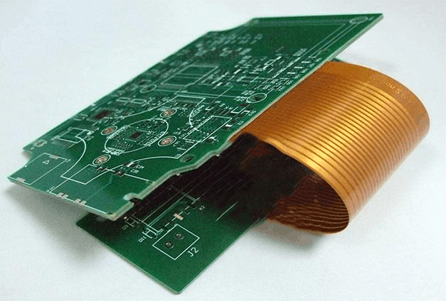
- Flex-rigid boards – integration of rigid and flexible sections
- Higher data-rate materials – >50 Gbps channels
- Automation and Industry 4.0 initiatives
Frequently Asked Questions
Why is FR4 the most commonly used PCB substrate material?
FR4 offers an unmatched balance of electrical performance, mechanical properties, heat resistance, ease of fabrication, and cost-effectiveness required in a PCB material. Its properties are suitable for the majority of general PCB applications across industries like consumer, telecom, industrial, auto, and medical electronics.
The global FR4 supply chain and manufacturing capacity is also highly developed and mature compared to other niche PCB materials. This enables economical high-volume production.
What are the alternatives to FR4 for PCB substrate?
Some alternatives are:
- High-frequency PCBs – PTFE, LCP, PPE, Rogers
- High-power/thermal PCBs – IMS, ceramic, aluminum
- High temperature – Polyimide
- Flexible PCBs – PET, PI, PEN
However, most materials are much more expensive than FR4. They are chosen only for specialized applications requiring properties not offered by FR4.
Can FR4 be used for outer layer PCB fabrication?
Yes, FR4 laminates clad with copper foil on one or both sides can be readily used for fabricating outer layer PCBs. The same lithography and etching process used for inner layers is followed.
The only difference is that for multilayer boards, the outer layers are bonded to the stack during lamination process. For double-sided or single-sided boards, the copper-clad FR4 laminate itself forms the substrate.
What are the different types of resins used in FR4?
The most common resin systems used in FR4 are:
- Bisphenol A epoxy resin
- Bisphenol F epoxy resin
- Tetrabromobisphenol A – for flame retardance
- Cyanate ester resin – high TG variant
The resin formulation affects properties like Tg, CTE, moisture absorption, and high temperature behaviour.
What is the difference between FR4 and CEM-1?
CEM-1 stands for composite epoxy material type 1, and is very similar to FR4. Both are glass-reinforced epoxy laminates. However, CEM-1 refers to low-Tg grade with Tg of only 105°C, while FR4 offers higher Tg in the range of 130 – 180°C. So FR4 provides better thermal performance.


Leave a Reply