Introduction to Phase-Locked Loops
A Phase-Locked Loop (PLL) is an electronic circuit that generates an output signal whose phase is related to the phase of an input signal. PLLs are widely used in radio, telecommunications, computers, and other electronic applications where it is necessary to generate a stable frequency or to recover a signal from a noisy communication channel.
The 565 Phase-Locked Loop is a monolithic integrated circuit (IC) designed for use in linear systems. It offers several advantages over other types of PLLs, including:
- Wide frequency range: The 565 can operate from a few hertz to hundreds of megahertz.
- High accuracy: The 565 can achieve phase lock with input signals as small as 50 mV.
- Low power consumption: The 565 typically consumes less than 10 mW of power.
- Easy to use: The 565 requires only a few external components to function.
How the 565 Phase-Locked Loop Works
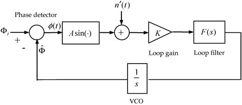
The block diagram of the 565 PLL is shown below:
        +-------+
Input-->|  PD   |-->LPF-->VCO-->Output
        +-------+
           ^  |
           |  |
           +--+
             |
             |
            +--+
            |  |
            |  v
            +--+
            |  |
            +--+
The 565 consists of three main components:
-
Phase Detector (PD): The phase detector compares the phase of the input signal with the phase of the VCO output. It generates an error signal proportional to the phase difference between the two signals.
-
Low Pass Filter (LPF): The low pass filter smooths the error signal from the phase detector, removing any high-frequency components. The output of the LPF controls the frequency of the VCO.
-
Voltage Controlled Oscillator (VCO): The VCO generates a periodic output signal whose frequency is determined by the voltage applied to its control input. The VCO output is fed back to the phase detector, forming a closed loop.
When an input signal is applied to the 565, the phase detector compares its phase with the phase of the VCO output. If the two signals are not in phase, the phase detector generates an error signal. The error signal is filtered by the LPF and applied to the VCO, causing the VCO frequency to change in the direction that reduces the phase difference. This process continues until the VCO frequency matches the input frequency and the loop is locked.
Applications of the 565 PLL
The 565 PLL finds use in a wide range of linear systems, including:
Frequency Synthesis
The 565 can be used to generate a stable, programmable frequency from a fixed reference frequency. By dividing the VCO output frequency and feeding it back to the phase detector, the 565 can multiply the reference frequency by a programmable factor.
For example, suppose we want to generate a 100 kHz signal from a 10 kHz reference. We can configure the 565 as follows:
- Set the VCO free-running frequency to 100 kHz
- Divide the VCO output by 10 and feed it back to the phase detector
- Apply the 10 kHz reference signal to the other input of the phase detector
When the loop locks, the VCO output will be exactly 100 kHz, phase-locked to the 10 kHz reference.
FM Demodulation
The 565 can be used to demodulate FM signals. In an FM system, the information is encoded in the instantaneous frequency of the carrier signal. The 565 can track the variations in carrier frequency and convert them back into the original modulating signal.
To use the 565 as an FM demodulator:
- Set the VCO free-running frequency to the center frequency of the FM signal
- Apply the FM signal to the input of the phase detector
- Take the demodulated output from the LPF
The output of the LPF will be a voltage proportional to the instantaneous frequency deviation of the FM signal, which is the original modulating signal.
Clock Recovery
In digital communication systems, the receiver must synchronize its clock with the transmitter in order to correctly sample the incoming data. The 565 can be used to extract the clock signal from the received data stream.
To use the 565 for clock recovery:
- Set the VCO free-running frequency to the nominal bit rate of the data
- Apply the received data to the input of the phase detector
- Take the recovered clock from the VCO output
The 565 will adjust the phase and frequency of the VCO until it matches the timing of the received data transitions. The VCO output will then be a clean, synchronized clock signal that can be used to sample the data.

Designing with the 565 PLL
To use the 565 in a linear system, the designer must select appropriate values for the external components that set the operating parameters of the PLL. The key parameters are:
- VCO free-running frequency
- Loop filter bandwidth
- Phase detector gain
- VCO gain
The choice of component values depends on the specific application and the characteristics of the input signal. Some general guidelines are:
- The VCO free-running frequency should be close to the expected input frequency to minimize the pull-in time of the loop.
- The loop filter bandwidth should be narrow enough to reject noise and interference, but wide enough to track expected variations in the input frequency.
- The phase detector gain and VCO gain should be chosen to provide adequate loop gain for reliable locking, but not so high that the loop becomes unstable.
The table below shows some typical component values for common applications:
| Application | VCO Frequency | Loop Filter Bandwidth | Phase Detector Gain | VCO Gain |
|---|---|---|---|---|
| FM Demodulation | 10.7 MHz | 100 kHz | 0.1 V/rad | 100 kHz/V |
| Frequency Synthesis | 1-100 MHz | 10 kHz | 0.1 V/rad | 1 MHz/V |
| Clock Recovery | 1-10 MHz | 1% of bit rate | 0.1 V/rad | 1 MHz/V |
Limitations of the 565 PLL
While the 565 is a versatile and reliable PLL IC, it does have some limitations that the designer should be aware of:
- The 565 is a linear PLL, meaning that it can only track input signals that are close to its free-running frequency. It cannot lock to signals that are far outside its capture range.
- The 565 has a relatively low maximum operating frequency of about 500 MHz. For higher frequencies, other types of PLLs such as digital PLLs may be more suitable.
- The 565 requires a clean, noise-free input signal for reliable operation. In noisy environments, pre-filtering of the input signal may be necessary.
- The 565 can consume significant power, especially at high frequencies. Power consumption can be reduced by using a higher supply voltage and lower loop gain, but this may compromise lock range and tracking performance.
Despite these limitations, the 565 remains a popular choice for many linear systems due to its simplicity, versatility, and low cost.

Conclusion
The 565 Phase-Locked Loop is a versatile and reliable IC that is well-suited for use in linear systems. Its wide frequency range, high accuracy, and low power consumption make it an attractive choice for applications such as frequency synthesis, FM demodulation, and clock recovery.
When designing with the 565, careful selection of external component values is necessary to optimize loop performance for the specific application. Designers should also be aware of the limitations of the 565, such as its linear nature and maximum operating frequency.
Overall, the 565 PLL is a valuable tool in the designer’s toolkit for building stable, high-performance linear systems.

Frequently Asked Questions
- What is the main advantage of the 565 PLL over other types of PLLs?
-
The main advantage of the 565 PLL is its simplicity and versatility. It requires only a few external components and can operate over a wide frequency range, making it suitable for a variety of applications.
-
How does the 565 PLL achieve phase lock with the input signal?
-
The 565 PLL achieves phase lock by comparing the phase of the input signal with the phase of the VCO output using a phase detector. The phase detector generates an error signal proportional to the phase difference, which is filtered and used to control the frequency of the VCO until the two signals are in phase.
-
What are some common applications of the 565 PLL?
-
Some common applications of the 565 PLL include frequency synthesis, FM demodulation, and clock recovery in digital communication systems.
-
What factors should be considered when selecting external component values for the 565 PLL?
-
When selecting external component values for the 565 PLL, designers should consider the expected input frequency, loop filter bandwidth, phase detector gain, and VCO gain. The choice of values depends on the specific application and desired loop performance.
-
What are some limitations of the 565 PLL that designers should be aware of?
- Some limitations of the 565 PLL include its linear nature, which limits its ability to track signals far outside its capture range, its relatively low maximum operating frequency of about 500 MHz, its sensitivity to noise on the input signal, and its potentially high power consumption at high frequencies.


Leave a Reply