 flexpcb.org
FLEXPCB.ORG / informational
Flex PCB Types: Compare the Construction
Get a Flex PCB Quote ↗Single-sided and double-sided
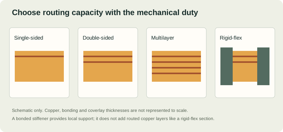
One conductive layer suits a simple interconnect when the routing can be completed without crossovers. A second layer adds routing freedom and can provide a reference conductor, but increases thickness and introduces interlayer connection requirements.
Multilayer construction
Additional copper layers help with dense routing and reference planes. The resulting stackup, bonding arrangement and copper distribution change bending behaviour. Agree the complete finished thickness and bending region before selecting a radius.
Rigid-flex and reinforced flex
Rigid-flex integrates interconnected rigid and flexible sections. A stiffener bonded to a flexible circuit provides local mechanical support without becoming another routed copper layer. Compare the installed system, including connectors, assembly fixtures and inspection.
Make the requirements reviewable.
| Define | Include in the review | Why it matters |
|---|---|---|
| Mechanical duty | Installed shape, bend location, motion and cycle target | Distinguishes installation bending from service fatigue |
| Construction | Layer order, copper, film, adhesive and coverlay | Establishes finished thickness and material compatibility |
| Interfaces | Connector thickness, pad finish and local reinforcement | Controls fit, assembly support and contact reliability |
| Acceptance | Dimensions, electrical test and applicable standard revision | Creates an agreed basis for inspection and quotation |
CONTINUE THE DESIGN REVIEW
Connect the decisions.
YOUR NEXT STEP
Bring the requirements.
Start the conversation.
Tell us what the circuit needs to do, how it will bend and when you need it. A complete build brief makes a quote easier to evaluate.
Preparing files?
Include Gerber and drill data, a fabrication drawing and stackup notes. Put related files in one ZIP. Add a BOM and placement file when assembly is required.