 flexpcb.org
FLEXPCB.ORG / informational
Flex PCB Stiffener: Connector Fit and Local Support
Get a Flex PCB Quote ↗Start with the supported interface
Define what the reinforcement must do. A connector termination may need a controlled insertion thickness; an assembly region may need mechanical support during handling and component placement. Those requirements can lead to different materials and outlines. Begin with the connector drawing, assembly method and installed support conditions. Do not select a stiffener solely because another board used the same thickness.
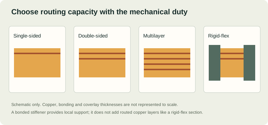
Distinguish stiffened flex from rigid-flex
A bonded PI or FR-4 stiffener adds local mechanical support. It is not another routed electrical layer. Rigid-flex integrates electrically interconnected rigid and flexible board regions and has different construction and transition requirements. Name the intended structure explicitly in the quote package so suppliers price the same design. If only connector thickness matching is needed, explain that function before specifying a more complex construction.
Include the attachment adhesive in the fit
The thickness at the supported interface includes the flexible circuit, attachment adhesive and stiffener. For example, a nominal 0.136 mm flex plus 0.200 mm reinforcement and 0.025 mm attachment adhesive totals 0.361 mm locally. This example does not establish that a particular connector will accept it. Compare the permitted thickness range, contact-side orientation and insertion depth from the actual connector drawing, including manufacturing tolerances.
Document the stiffener outline and transition
Show the stiffener on its own drawing layer with a clear legend, dimensions and registration references. Identify the side of attachment, material, thickness, adhesive system and any required openings. Mark the allowed bending area and coordinate the stiffener edge with the fabricator. Keep assembly access and tool clearance in the review: a region that is easy to fabricate may be difficult to insert into the final housing.
Check the assembled condition
Inspect representative samples at the supported interface and in the final mechanical parts. Review flatness, connector engagement, support during assembly and handling damage. If the stiffener material or attachment method changes, reconsider the mechanical and thermal conditions rather than assuming equal nominal thickness gives equal performance. Include the approved construction and drawing revision in repeat orders.
Make the requirements reviewable.
| Define | Include in the review | Why it matters |
|---|---|---|
| Mechanical duty | Installed shape, bend location, motion and cycle target | Distinguishes installation bending from service fatigue |
| Construction | Layer order, copper, film, adhesive and coverlay | Establishes finished thickness and material compatibility |
| Interfaces | Connector thickness, pad finish and local reinforcement | Controls fit, assembly support and contact reliability |
| Acceptance | Dimensions, electrical test and applicable standard revision | Creates an agreed basis for inspection and quotation |
CONTINUE THE DESIGN REVIEW
Connect the decisions.
YOUR NEXT STEP
Bring the requirements.
Start the conversation.
Tell us what the circuit needs to do, how it will bend and when you need it. A complete build brief makes a quote easier to evaluate.
Preparing files?
Include Gerber and drill data, a fabrication drawing and stackup notes. Put related files in one ZIP. Add a BOM and placement file when assembly is required.