 flexpcb.org
FLEXPCB.ORG / informational
Flex PCB Bend Radius: Static and Dynamic Design
Get a Flex PCB Quote ↗Define the radius you are measuring
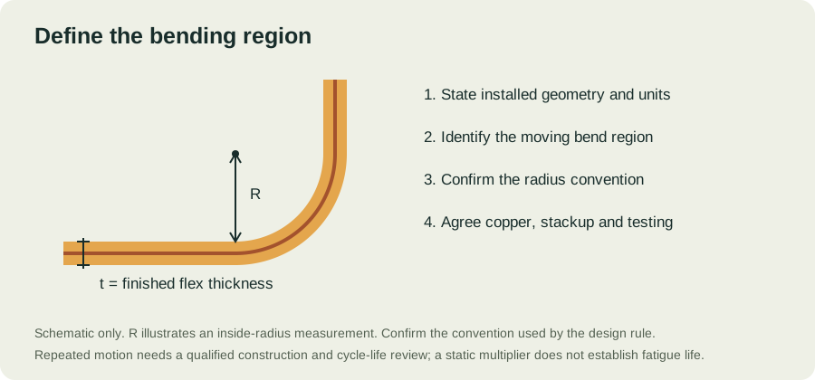
A bend requirement needs a drawing, a reference surface and a tolerance. The inside surface, copper layer and neutral axis do not have the same radius. Mark the available envelope in the installed assembly, then confirm which radius convention the selected design rule uses. Include adjacent supports and the transition from flat to curved material. A dimension on a flat fabrication drawing alone cannot describe the installed shape.
Use finished thickness in the bending region
The relevant thickness is the complete flexible construction at the bend: copper, dielectric films, adhesives, coverlays and any shielding present there. A laminate core thickness is only one component. Do not add a connector stiffener to the bending-region thickness when the stiffener ends outside that region. Instead, review its edge as a separate mechanical transition. Use the fabricator's finished stackup and tolerances for the released drawing.
A static screening example
The published Minco design guide gives static screening ratios of 6 times thickness for single-sided, 12 times for double-sided and 24 times for multilayer constructions. Our calculator uses these ratios as a preliminary reference. A double-sided circuit with a 0.15 mm finished flex thickness therefore gives 12 × 0.15 = 1.80 mm. This arithmetic is not an IPC-2223 calculation, a qualified fatigue result or an approval to manufacture. Confirm applicability and final geometry with the fabricator before adopting it as a requirement.
Treat repeated motion as a separate design task
A design that survives installation may fail when cycled. Record the motion range, direction, frequency, intended life, temperature and constraints at both ends. Identify any twisting, vibration or sliding contact imposed by the enclosure. The combination of copper foil, plating, layer positions and mechanical strain needs a qualified review. Our tool deliberately returns an engineering-review message for dynamic use because one layer-count multiplier cannot establish cycle life.
Make a representative validation sample
Test the released construction in representative mechanical supports. Record the initial electrical condition, how the sample is restrained, the actual bend geometry and the acceptance criteria. Document the number of cycles and the environmental conditions. If the stackup, copper system, protective layers or support geometry changes, assess whether the previous result still represents the product. A successful demonstration on an unrepresentative sample is not a production qualification.
Make the requirements reviewable.
| Define | Include in the review | Why it matters |
|---|---|---|
| Mechanical duty | Installed shape, bend location, motion and cycle target | Distinguishes installation bending from service fatigue |
| Construction | Layer order, copper, film, adhesive and coverlay | Establishes finished thickness and material compatibility |
| Interfaces | Connector thickness, pad finish and local reinforcement | Controls fit, assembly support and contact reliability |
| Acceptance | Dimensions, electrical test and applicable standard revision | Creates an agreed basis for inspection and quotation |
CONTINUE THE DESIGN REVIEW
Connect the decisions.
YOUR NEXT STEP
Bring the requirements.
Start the conversation.
Tell us what the circuit needs to do, how it will bend and when you need it. A complete build brief makes a quote easier to evaluate.
Preparing files?
Include Gerber and drill data, a fabrication drawing and stackup notes. Put related files in one ZIP. Add a BOM and placement file when assembly is required.