 flexpcb.org
Smartwatch Flex PCB Routing: Keep Motion Away from Solder Joints
UPDATED October 9, 2026
Discuss your flex PCB project →
Smartwatch flex PCB routing starts with a mechanical question: which parts of the interconnect move after the watch has been assembled? A display tail folded into a supported position has a different duty from a circuit that crosses a moving strap attachment. Treating both as the same bend can leave a soldered connection carrying loads that should have been taken by the enclosure.
This article uses an illustrative watch assembly to show how to separate those duties. It is a design-review method, not a tested product layout or a claimed manufacturing capability. For the broader packaging context, see our wearable flex PCB requirements.
Start with three zones on the mechanical drawing
Before routing copper, give the electrical and mechanical teams the same annotated drawing. Mark a supported electronics zone inside the case, a bend-to-install connection to the display, and any region that experiences movement during use. The boundaries should describe physical supports and movement, rather than simply following the outline of the flex.
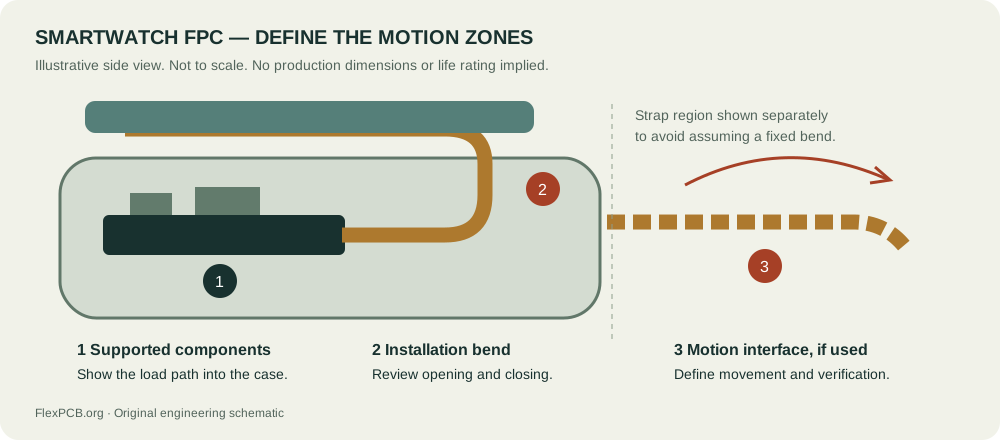
| Zone | Question to answer | Evidence to put in the design package |
|---|---|---|
| Supported case electronics | Where do connector insertion and component loads go? | Support surfaces, fasteners or approved attachment areas, with assembly access shown. |
| Display installation bend | What happens while the display is opened, connected and closed? | The assembly sequence and installed shape, including the closest housing features. |
| Moving strap interface, if present | Does a circuit actually cross this interface, and how does it move? | A movement envelope, restraint locations and a representative verification plan. |
The table prevents a common communication error: the mechanical drawing shows the final closed watch, while the electrical drawing assumes the tail can be connected in that position. Walk through the connection operation with both drawings visible. If the connector can only be reached while the display is lifted, that temporary position belongs in the review too.
Keep the load path visible
Minco’s flex design guide distinguishes installation bending from dynamic use and discusses circuit geometry, bend regions and reinforcement as connected design choices. Those are useful starting points, but supplier guidance is not a qualification result for a particular watch. Use the guide to frame questions for the selected construction, then record the agreed answers in the fabrication package. Minco Flex Circuits Design Guide.
For the illustrative assembly, trace the force from the display or strap back into the housing. Draw an arrow for each movement and mark the feature expected to restrain it. If an arrow ends at a solder pad because there is no other restraint, revisit the layout. A longer tail alone does not define where it will bend; it may instead touch the case, fold at an edge or move into a connector latch.
Review the support with the assembly partner. A feature that holds the circuit well in the finished watch may obstruct solder-paste printing, placement or inspection before installation. Keep the flex PCB design requirements tied to both the manufacturing state and the installed state.
Choose the connector before freezing the tail
Pitch is only one part of a flex-tail interface. Confirm the contact side, exposed contact geometry, permitted cable thickness, stiffener position and access to the actuator. Show the viewing direction and pin numbering on the connection drawing so that a folded tail cannot hide a mirrored interface.
Connector performance also depends on the specified mating circuit. For example, Molex’s 505278 product specification presents retention-force reference data for particular FFC/FPC constructions and notes that the cable specification affects the result. Those values are an example of why the exact interface matters, not a recommendation to use that connector or cable thickness in this watch. Molex 505278 product specification, sections 7 and 9.
Give the operator a supported place to handle the tail, and check the insertion direction in the actual enclosure. During a design review, ask someone who did not draw the circuit to describe the connection sequence using only the assembly drawing. Any missing step is a documentation issue to resolve before the prototype arrives.
Turn the movement into a reviewable test question
For a tail folded once during assembly, the first question may be fit and repeatable installation. For a circuit crossing a moving interface, the question changes to behavior over the specified movement and environment. Write the test objective before choosing a fixture or a cycle count.
- Record the two end restraints and the allowed movement between them.
- Identify the circuit revision, stackup and protective layers used in the sample.
- Describe the housing surfaces that could touch the circuit.
- Define the electrical functions to monitor and what observation would constitute a failure.
- Record the inspection method and what happens to a failed sample before it is handled or opened.
Our bend-radius screening tool can help organize a static bend discussion. Its result is not a repeated-motion life prediction. The moving strap region needs its own engineering assessment; entering the static portion’s thickness into a calculator does not validate the entire assembly.
Calculate clearance from a common datum
A drawing that shows daylight around a nominal flex route does not establish minimum clearance. For an early packaging review, define a housing datum and measure both the obstruction and the circuit envelope from it. The envelope should include the installed circuit shape, the expected assembly variation and any approved movement. Do not mix a dimension from the metal case with a dimension from the display glass unless the relationship between those references is included in the calculation.
Consider an original, hypothetical one-dimensional example. A boss surface is located 2.00 mm from a case datum, with a positional allowance of plus or minus 0.10 mm. The closest surface of a supported flex envelope is at 1.50 mm from that same datum, with an allowance of plus or minus 0.15 mm. The nominal separation is 0.50 mm. If both dimensions move toward one another, the minimum calculated separation is 2.00 minus 0.10 minus 1.50 minus 0.15, or 0.25 mm. These values are invented for the example and are not manufacturing recommendations.
If the design team separately allocates 0.20 mm for additional motion toward the boss, only 0.05 mm remains in this simplified budget. That result does not establish acceptance. It identifies a question: can the assembly maintain the required separation once movement, inspection uncertainty and other relevant contributors are included? The team must define the actual clearance requirement. If the motion envelope already includes positional variation, adding the same allowance again would double count it. Write down what each number contains before adding it to the stack.
This linear subtraction is useful only for the stated geometry. A tail rotating around a support, twisting through a corner or contacting an inclined surface needs a suitable geometric assessment. Inspect intermediate display positions as well as the two endpoints. A route can clear the enclosure when fully open and fully closed while crossing an obstruction halfway through the operation. Capture the controlling position in the drawing so that later enclosure changes can be reviewed against the same condition.
Write the assembly sequence as a set of observable states
For a hypothetical display connection, begin with the case supported and the display held at a defined service angle. Identify the surface the operator can touch, the connector actuator position and the direction in which the tail enters. Next describe how the operator verifies seating before closing the actuator. Finally describe the movement that places the display into the case. Each state should show where the circuit is supported and where freedom of movement remains. A photograph of only the finished assembly cannot answer these questions.
Use the sequence to decide whether a proposed restraint is installed before or after the tail is connected. A restraint installed early may improve positional repeatability but prevent access to the connector. A restraint installed late may require the operator to move an already connected tail. Neither choice is automatically correct. Build a simple nonfunctional packaging mock-up to evaluate reach and visibility, then use representative circuits for questions involving actual forming behavior. Record which conclusions came from the mock-up and which still require production-intent material.
Separate seating verification from an electrical power-on check. A display that operates during one brief check does not document how the tail was inserted or whether a restraint was fitted. Define visible assembly evidence, such as an agreed witness feature or an inspection view, with the connector and assembly suppliers. Avoid inventing an insertion depth from the nominal contact length. The selected connector drawing and mating-circuit specification govern the interface.
Plan the return path through service and failure analysis
If the watch is intended to be opened for repair, document the reverse sequence before releasing the original assembly. Identify what must be removed to reach the actuator, what supports the display during disconnection and whether any attachment material must be replaced. Decide explicitly whether the flex is reusable after service. That decision belongs to the product’s verification and service requirements; it cannot be inferred from the fact that a technician managed to reconnect a prototype.
For investigation of an intermittent display fault, preserve the installed condition before pulling on the circuit. Record the display position, restraint condition and connector engagement that can be observed without disturbing them. Then follow an agreed disassembly procedure. Otherwise, an investigation may introduce a new crease or change the contact condition and lose the evidence needed to distinguish an installation problem from a circuit problem. Include the sample identifier and assembly history in the inspection record.
A useful prototype record pairs a specific question with a specific observation. For example, ask whether the tail contacts the screw boss during the defined closure path, rather than whether the flex looks acceptable. Record the starting position, route revision, sample construction, operator sequence and observation method. If no contact is observed, state the conditions examined. Do not turn that limited result into a claim about every tolerance combination, every environmental condition or the full service life of the watch.
A practical release review
Imagine that the first packaging review finds the display tail clear of the housing when closed, but touching a screw boss while the display is opened for connection. Record the observation as a specific conflict, with the position of the display and the circuit revision. Compare a change to the opening sequence, a different restraint position or a revised tail route. Recheck connector access and the closed shape after each change.
This is an illustrative decision process, not a reported test. Its value is that each proposed fix has an observable question attached to it. The team can decide which prototype or fixture will answer that question instead of declaring the design acceptable because the circuit can be folded by hand.
For a project review, prepare the flat outline, installed views, connector part number, complete stackup and the movement description. Include assembly quantity and the questions the prototype must answer. Send your smartwatch flex PCB requirements so the construction and review scope can be discussed together.